Integrated RF MEMS switch

A switch and mobile switch technology, applied in the field of radio frequency technology and micro-electromechanical systems, can solve the problems of the adverse effect of switch RF performance, switch impurity pollution, slowing down the operation speed, etc., to improve processing reliability, resist external pollutants, reduce The effect of process complexity

Inactive Publication Date: 2006-01-04
BEIJING UNIV OF POSTS & TELECOMM
View PDF0 Cites 21 Cited by
  • Summary
  • Abstract
  • Description
  • Claims
  • Application Information

AI Technical Summary

Problems solved by technology

If the length of the force arm is kept constant, the support point 2 will inevitably move outward, so that the area of ​​the entire chip will increase
In addition, when the switch is cut off, the cantilever beam end contact points 8a, 5 and 8b cannot effectively contact the points 7a, 6a, 6b and 7b on the coplanar waveguide, thus deteriorating the isolation or insertion loss of the switch
[0006] also, Figure 1A , Figure 1B , Figure 1C These three types of switches all have a common defect, that is, the freely suspended cantilever beam is affected by the shortcomings of the mechanical characteristics. Since one end is suspended in the air, uncontrolled mechanical vibration will occur during use, which will affect the RF performance of the switch. Negative Effects
Due to the inherent torsion of the contact end of a single cantilever beam switch structure, it is impossible to ensure that the bridge electrode on the cantilever beam is always in linear contact with the transmission line on the substrate. This type of switch will exhibit an asymmetrical electrical characteristic, and, due to the contact resistance presence, will slow down operation and limit the efficiency of these RF MEMS switches
These switches are susceptible to contamination from impurities generated during manufacture and use

Method used


Image

  • Integrated RF MEMS switch
  • Integrated RF MEMS switch
  • Integrated RF MEMS switch

Examples


Embodiment Construction

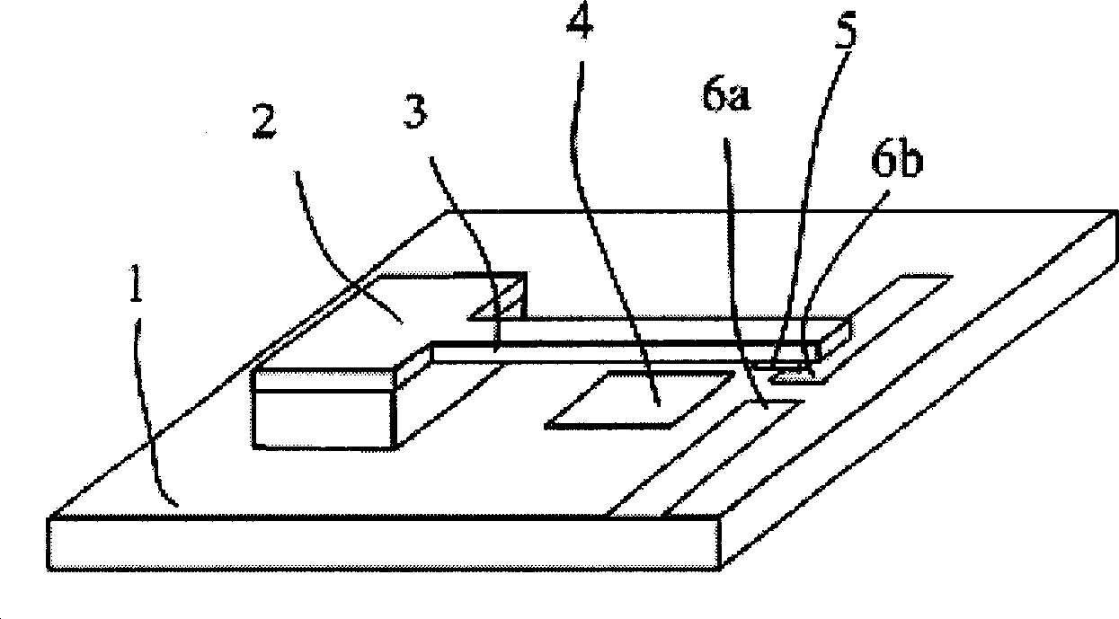
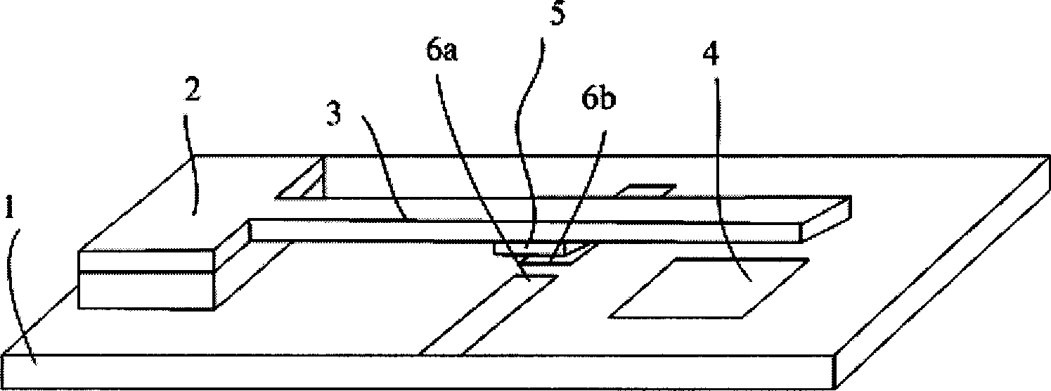
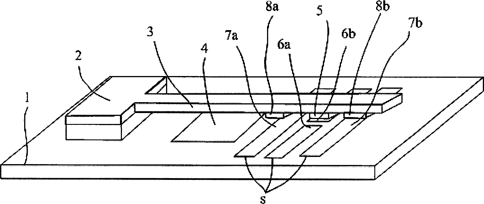
[0026] Preferred embodiments of the present invention will now be described with reference to the accompanying drawings. In the figure, because of the symmetry of the structure, the elements with the same structure, shape and function are represented by the same number symbol, and English letters such as a, b, and c are added after the number to distinguish each element.

[0027] The invention is an RF MEMS switch applied to high-speed electrostatic drive and capable of resisting external pollutants.

[0028] According to a preferred embodiment of the invention, the switch comprises a MEMS part 50 and an RF part 40 . Referring to the schematic diagram of a preferred embodiment of the present invention, wherein, Figure 2A is the top view of the MEMS part, Figure 2B yes Figure 2A The cross-sectional view of the A-A' direction in the middle, Figure 2C is a schematic diagram of the three-dimensional structure of the MEMS part of the preferred embodiment of the present inve...


PUM


Abstract

The RF switch based on micro electromechanical technology includes micro mechanism (MEMS) part and RF part, and has mobile switch structure for the switching function is set on the MEMS substrate. The MEMS part and RF part are first manufactured separately, and the MEMS substrate and RF substrate are then aligned and bonded together. The switch includes several mobile electrodes and has two kinds of drive states including upward drawing state and downward drawing state. The switch in the technological scheme of the present invention has fast switching speed, low drive voltage, high stability and relatively simple manufacture process with high outer contamination resistance.

Description

technical field [0001] The present invention relates to the technical field of radio frequency technology and micro-electro-mechanical system (micro-electro-mechanical system, MEMS). Specifically, the present invention relates to a radio frequency (RF) switch developed using micro-electromechanical system (MEMS) technology. Background technique [0002] Radio frequency microelectromechanical system (RF MEMS) switch is one of the basic components of electronic circuit systems such as wireless communication, and it is widely used in radar detection and wireless communication. RF MEMS switches have a variety of drive methods, including electrostatic drive, electromagnetic drive, thermoelectric drive, piezoelectric drive, and shape memory alloy drive. Among them, electrostatic drive has attracted widespread attention because of its simple structure, easy processing and compatibility with IC technology. Compared with traditional solid-state switches com...

Claims


Application Information

Patent Timeline
Patent Type & Authority Applications(China)
IPC IPC(8): H01H59/00H01P1/10
Inventor 万江文周玉娇
Owner BEIJING UNIV OF POSTS & TELECOMM
Why Eureka
Try Eureka