Azimuth measuring instrument with spin valve giant magnetoresistance element

A spin valve, giant magnetoresistance technology, applied in the size/direction of the magnetic field, measuring device, measuring magnetic variables and other directions, can solve the problems of high power consumption, low resistance, increase the size of the azimuth measuring instrument, etc., to simplify manufacturing Process, easy to manufacture, achieve anisotropic effects

Inactive Publication Date: 2006-01-18
HITACHI METALS LTD
View PDF1 Cites 8 Cited by
  • Summary
  • Abstract
  • Description
  • Claims
  • Application Information

AI Technical Summary

Problems solved by technology

[0005] Furthermore, since it is necessary to detect the external magnetic field (earth magnetism, etc.) ) sensitivity
This necessitates the need for relatively wide MR elements, but wider MR elements have lower resistance and greater power dissipation when the voltage used for measurement is applied to the MR element pair
Therefore, the magneto-resistive elements must be elongated to increase their resistance, but wider and longer magneto-resistive elements will have correspondingly larger square dimensions, which will necessarily increase the size of the azimuth measuring instrument

Method used


Image

  • Azimuth measuring instrument with spin valve giant magnetoresistance element
  • Azimuth measuring instrument with spin valve giant magnetoresistance element
  • Azimuth measuring instrument with spin valve giant magnetoresistance element

Examples


Embodiment 2

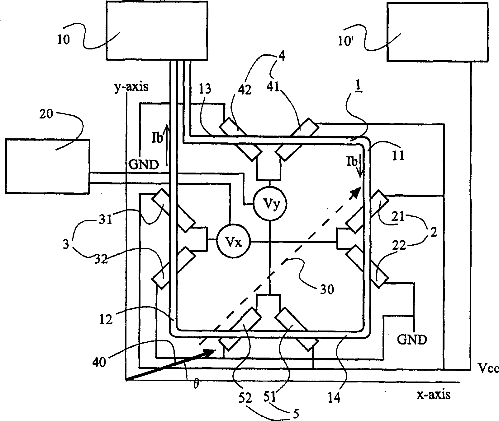
[0093] Figure 13 The azimuth measuring instrument according to Embodiment 2 of the present invention is shown in the form of a circuit diagram. In this embodiment, the longitudinal direction of one spin-valve giant magnetoresistance element of each spin-valve giant magnetoresistance element pair intersects only one of the pair of opposite sides of planar coil 1 substantially at 45 degrees. In addition, the longitudinal direction of the other spin-valve giant magnetoresistance element of each spin-valve giant magnetoresistance element pair intersects only one pair of opposite sides and the other of the planar coil 1 substantially at 45 degrees. Therefore, one spin valve giant magnetoresistance element 21 of the spin valve giant magnetoresistance element pair 2 intersects with one side 11 of the planar coil 1, and the other spin valve giant magnetoresistance element of the spin valve giant magnetoresistance element pair 2 22 intersects side 12 opposite side 11. A spin valve g...


PUM


Abstract

An azimuth meter using spin-valve giant magneto-resistive elements, which is simple in manufacturing process, can be made compact in size and contribute to power saving, is disclosed. The azimuth meter comprises a quadrilateral plane coil having two pairs of parallel opposed sides and four spin-valve giant magneto-resistive element pairs, each pair of the elements disposed on a plane parallel to the coil. The longitudinal directions of two elements of each pair orthogonally cross each other, and cross only a respective side or only the same side of a pair of the opposed sides of the plane coil at substantially 45 degrees. The pinned layer of one of the two elements is magnetized in its longitudinal direction, and that of the other element is magnetized in the same direction as the pinned layer of that one element. The paired elements are connected to each other at one end. While a voltage for measurement is being applied between the other ends, a midpoint potential is taken out of the ends of the elements connected to each other to determine an azimuth.

Description

technical field [0001] The present invention relates to an azimuth measuring instrument using a spin valve giant magnetoresistive element, and more particularly to an azimuth measuring instrument for measuring an azimuth while applying a bias magnetic field to a spin valve giant magnetoresistive element . Background technique [0002] The present applicant has applied for a patent on an azimuth measuring instrument combining an anisotropic magneto-resistive element with a planar coil, and this application is registered as US Patent 6,556,007. The azimuth measuring instrument disclosed in US Pat. No. 6,556,007 has a substantially square planar coil 1 and 8 magneto-resistive elements 61, 62, 71, 72, 81, 82, 91, 92 parallel on the plane and close to the planar coil, such as Figure 14 is an exploded perspective view. Two of the magneto-resistive elements (eg 61 and 72 ) cross at substantially 45 degrees to one side of the planar coil (eg 11 ) and the longitudinal directions of...

Claims


Application Information

Patent Timeline
Patent Type & Authority Applications(China)
IPC IPC(8): G01R33/02G01R33/09
CPCG01R33/093B82Y25/00G01R33/0206G01C17/32
Inventor 阿部泰典铃木和生
Owner HITACHI METALS LTD
Why Eureka
Try Eureka