Fuel cell system

A fuel cell system and fuel cell technology, applied in fuel cells, fuel cell additives, fuel cell heat exchange, etc., can solve the problems of reduced power generation capacity and concentration, and achieve the effect of realizing power generation capacity

Inactive Publication Date: 2006-02-01
SANYO ELECTRIC CO LTD
View PDF1 Cites 7 Cited by
  • Summary
  • Abstract
  • Description
  • Claims
  • Application Information

AI Technical Summary

Problems solved by technology

In this way, when the methanol aqueous solution flows back into the fuel supply path, even if the pump is operated next time, the diluted methanol aqueous solution will return to the buffer tank, resulting in a sharp drop in concentration and a decrease in power generation capacity.
[0008] In addition, this kind of problem also occurs when air bubbles are mixed into the fuel supply path.
However, when handling is facilitated by making the fuel container a detachable bunker, no matter what you do, air bubbles will enter the fuel supply path when the fuel container is replaced, etc.

Method used


Image

  • Fuel cell system
  • Fuel cell system
  • Fuel cell system

Examples


Embodiment 1

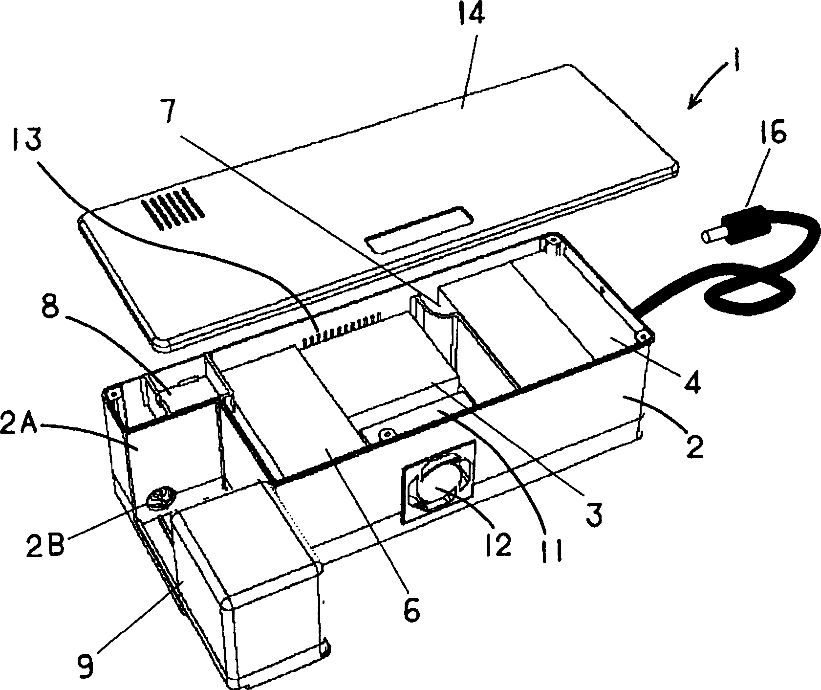
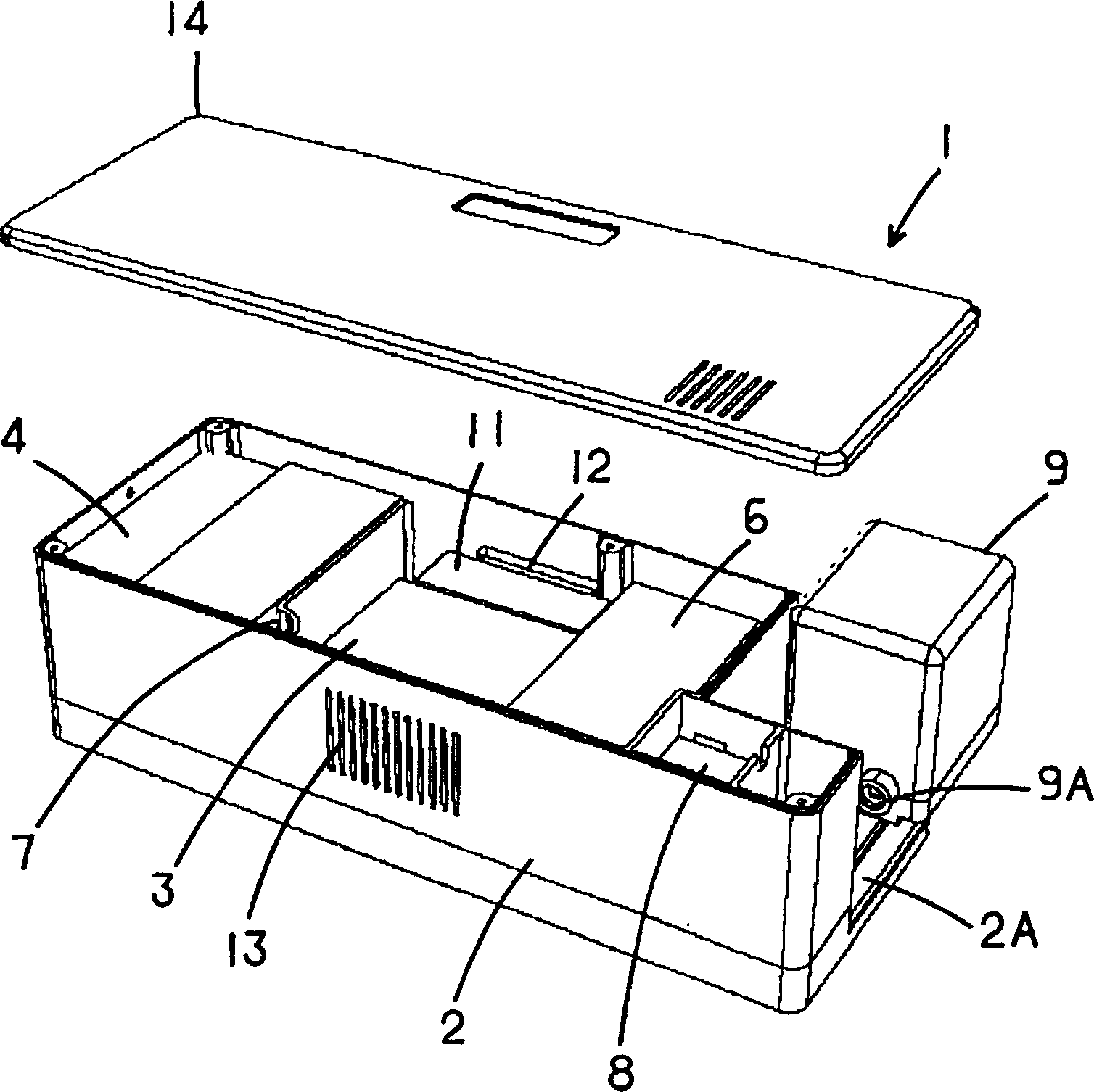
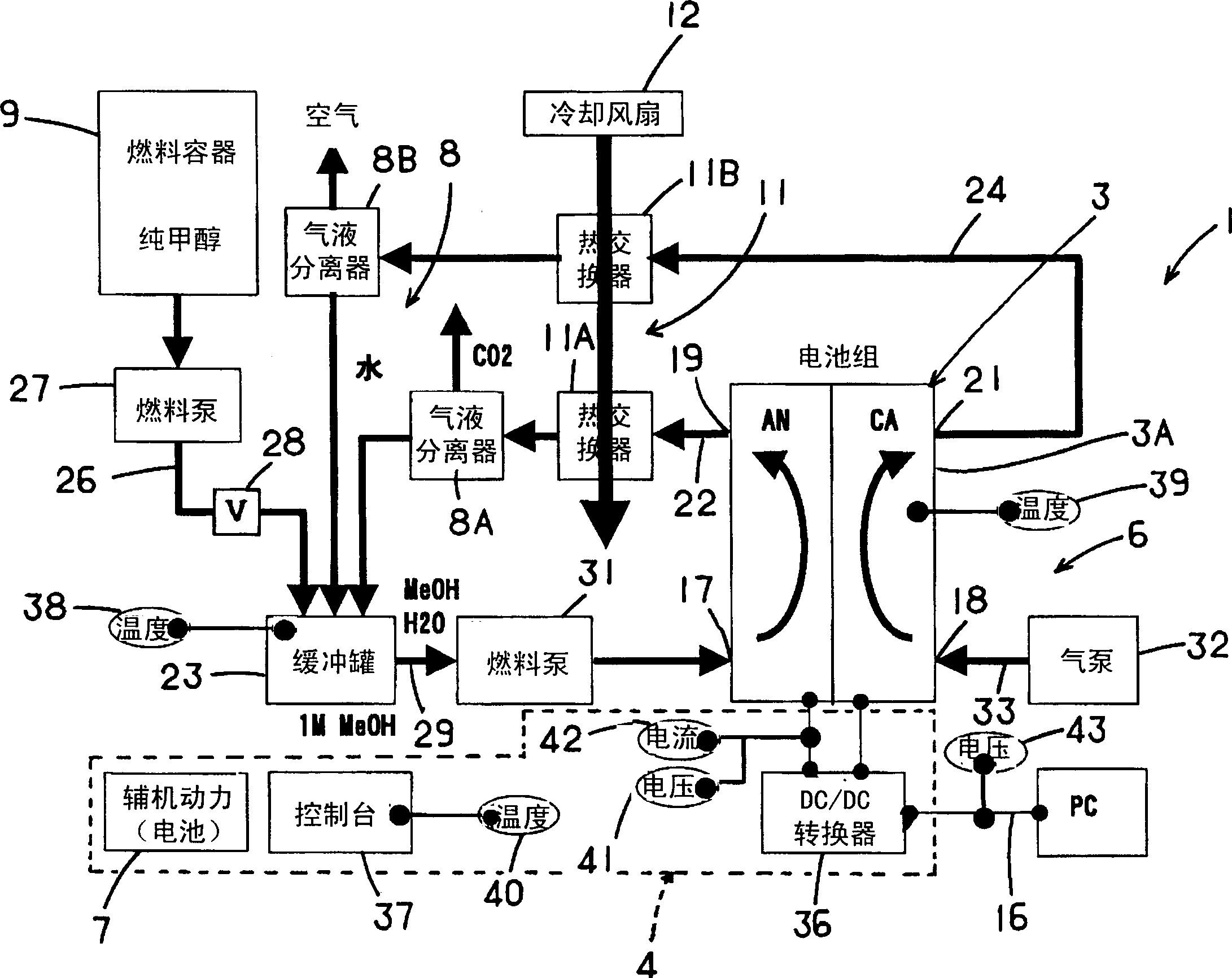
[0054] figure 1 A front perspective view showing a fuel cell system 1 using an embodiment of the present invention, figure 2 Represents the same rear perspective view, image 3 A configuration diagram of the fuel cell system 1 is shown. The fuel cell system 1 of the embodiment is a so-called Direct Methanol Fuel Cell (DMFC) that generates electricity by using methanol as a liquid fuel and electrochemically reacting the methanol with air as an oxidant in a fuel cell cell. The system is compact in overall size so that it can be used as a power source for a portable notebook personal computer, for example.

[0055] That is, the fuel cell system 1 is figure 1 and figure 2 A fuel cell (battery pack) 3 is mounted in the approximate center of the box 2 shown, a control unit 4 is provided on one side in the longitudinal direction, and an auxiliary unit 6 is provided on the opposite side. In addition, an auxiliary power (secondary battery) 7 is provided between the control unit ...

Embodiment 2

[0079] under, Figure 9 A configuration diagram showing the vicinity of the fuel supply pipe 26 of the fuel cell system 1 according to another embodiment of the present invention. and, Figure 9 The structure of the fuel cell system 1 at this time from the fuel container 9 to the buffer tank 23 is extracted and shown, and the other parts are the same as image 3 same. At this time, on the fuel supply pipe 26, instead of image 3 , Figure 4 In this case, the solenoid valve 28 is connected to the discharge side and the suction side of the fuel pump 27 as a three-way valve 51 (solenoid valve 1 ) and a three-way valve 52 (solenoid valve 2 ) as flow path switching means. One end of the air bubble recovery pipe 54 is also connected to the three-way valve 51. One end of the air bubble recovery pipe 54 communicates with the upper part of the fuel supply pipe 26, and the other end of the air bubble recovery pipe 54 communicates with the sub-fuel tank formed in the air-opening type...


PUM


Abstract

In a fuel cell system which dilutes a liquid fuel to supply the diluted liquid fuel to an anode, it is intended to achieve stable electricity generation capacity. The fuel cell system generates electricity by an electrochemical reaction between the liquid fuel and an oxidant, and this system comprises a cell which generates electricity by the electrochemical reaction; a fuel container containing the liquid fuel of high concentration; and a buffer tank which dilutes the liquid fuel in the fuel container to supply the diluted liquid fuel to the anode of the cell, wherein an electromagnetic valve is provided in a fuel supply path between the fuel container and the buffer tank to prevent the liquid fuel from flowing back from the buffer tank to the fuel container.

Description

technical field [0001] The present invention relates to a fuel cell system that supplies liquid fuel to fuel cell cells to generate electricity. Background technique [0002] In recent years, from the viewpoint of environmental problems and energy saving, the development of fuel cells that generate electricity by utilizing the electrochemical reaction of fuel and oxidant has been actively carried out. The fuel cell is a device that generates electric energy from fuel and an oxidant, and can obtain high power generation efficiency. In addition, the main features of the fuel cell include the following features, that is, since it does not directly generate electricity through the process of thermal energy or kinetic energy like conventional power generation methods, high power generation can be expected even if it is small-scale. Efficiency, and since there is little discharge of nitrogen compounds, etc., there is little noise or vibration, so the environment is good. [0003...

Claims


Application Information

Patent Timeline
Patent Type & Authority Applications(China)
IPC IPC(8): H01M8/00
CPCH01M8/04014H01M8/2475H01M8/1011H01M8/04208Y02E60/523H01M8/04186H01M8/06Y02E60/50H01M8/04
Inventor 藤田悟朗株本浩挥南浦武史
Owner SANYO ELECTRIC CO LTD
Why Eureka
Try Eureka