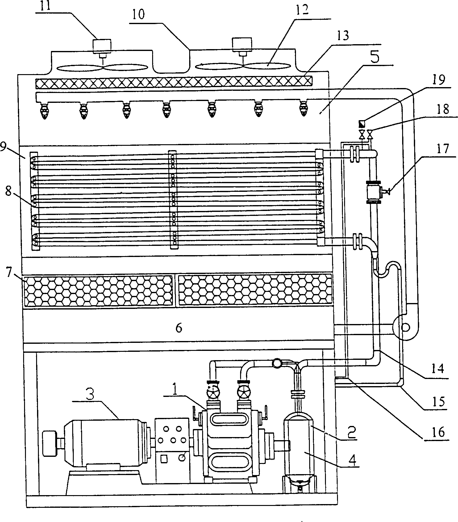
Condenser set of evaporated compressor

A technology of condensing units and compressors, applied in evaporators/condensers, compressors, irreversible cycle compressors, etc., can solve the problems of cooling tower power increase, large power consumption, and heavy workload, and achieve steel material consumption Effects of reduction, improvement of automation, and construction area saving

Inactive Publication Date: 2006-03-15
金兴才
View PDF0 Cites 5 Cited by
  • Summary
  • Abstract
  • Description
  • Claims
  • Application Information

AI Technical Summary

Problems solved by technology

Due to the use of vertical condensers, and the need for cooling towers and circulating pumps, the overall layout is huge, the floor area is large, the bulk pipes are long, there are many valves, the resistance is large, the cooling speed is slow, the distributed operation, and the workload is large. Difficult to control, adopting shell-and-tube condenser requires a large amount of water to exchange heat with the medium, so the amount of circulating water is large, the head of the pump is high, the power consumption is large, the power of the cooling tower increases, and there is no water eliminator, the annual maintenance cost increases , energy consumption, consumables, high operating costs, and pollute the environment

Method used


Image

  • Condenser set of evaporated compressor

Examples


Embodiment Construction

[0008] Referring to the accompanying drawings, its structure includes a condenser, a compressor 1, a liquid receiver 3, an oil collector 4, and an oil separator 2. After the ammonia compressor is started by the compressor 1, it produces refrigerated oil and refrigerated liquid, which are mixed to generate high pressure. , one way is sent to oil collector 4, and the mixed gas generated by the other way is sent to oil separator 2; The liquid flows into the liquid receiver 3; the oil separator 2 decomposes the mixed gas produced by the compressor 1, and the refrigerated liquid gas is sent to the condenser, and after the condenser is cooled by cooling water, the gas is converted into liquid and flows upward into the liquid receiver 3. The lower liquid and oil are separated again and one way flows into the oil separator 2, and the other way flows into the liquid reservoir 3. The condenser is an evaporative condenser 5, and the spray pipe in the evaporative condenser 5 is connected t...


PUM


Abstract

An evaporative compressor condensing machine set comprises a condenser, a compressor, a liquid-storage container, an oil catcher and an oil separator. The condenser is an evaporative condenser, in which the spray pipe is connected with one end of the spray pump. The other end of the spray pump is in communication with the pool. On the spray pipe, several nozzles are mounted, and under which a coiler group consists of the elliptic pipes. There is a window and the spray pool under the evaporation coil group.

Description

technical field [0001] The invention relates to an evaporative compression condensing unit, which belongs to the technical field of refrigeration. Background technique [0002] The existing technology, such as LN-75 vertical cooling, its structure is that after the ammonia compressor is started, the refrigerant oil and refrigerant liquid are mixed to generate high pressure, and one path is sent to the oil collector, and the mixed gas generated by the other path is sent to the oil collector. Splitter. The oil collector decomposes the remaining oil and gas. After the oil is concentrated and put into the barrel, it is added to the refrigerator, and the refrigerant flows into the liquid reservoir. The oil separator decomposes the mixed gas generated by the compressor, and the refrigerant The gas is sent into the vertical condenser, and after the vertical condenser is cooled by the cooling water, the gas is converted into liquid, which flows into the liquid receiver at the top, ...

Claims


Application Information

Patent Timeline
Patent Type & Authority Applications(China)
IPC IPC(8): F25B1/00F25B39/04
Inventor 金兴才
Owner 金兴才
Why Eureka
Try Eureka