Radiator with uniform temperature hot cavity

A heat dissipation device and cavity technology, applied in the cooling of instruments, components of instruments, cooling/ventilation/heating transformation, etc., can solve the problems of drying out at heating points and damage to plate heat pipes, etc.

Inactive Publication Date: 2006-03-15
DELTA ELECTRONICS INC
View PDF0 Cites 1 Cited by
  • Summary
  • Abstract
  • Description
  • Claims
  • Application Information

AI Technical Summary

Problems solved by technology

Therefore, in order to quickly export heat energy, the thickness of the capillary structure is reduced. However, although this method can increase the conduction speed, when the heat source gene

Method used


Image

  • Radiator with uniform temperature hot cavity
  • Radiator with uniform temperature hot cavity
  • Radiator with uniform temperature hot cavity

Examples


Embodiment Construction

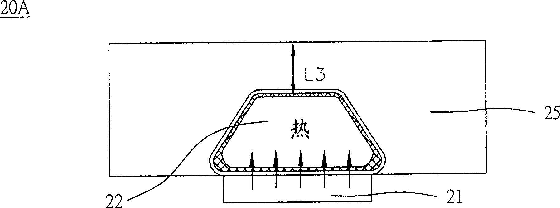
[0032] Please refer to Figure 2A , which shows a schematic diagram of a heat dissipation device according to a preferred embodiment of the present invention. The heat dissipation device 20A is applied to a heat source 21 , that is, a heat-generating electronic component 21 . The heat dissipation device 20A includes a vapor chamber 22 and a heat sink 25 . The heat uniform chamber 22 is directly attached to a heat source 21 to transfer heat from the heat-generating electronic component 21 to the radiator 25, and the radiator 25 is covered on and around the heat uniform chamber 22, The heat of the electronic component 21 can be quickly transferred to other places through the heat equalization cavity 22 and the heat sink 25 . The heat source 21 is, for example, a heating electronic component 21, such as CPU, transistor, server, high-end graphics card, hard disk, power supply, driving control system, multimedia electronic mechanism, wireless communication base station, high-end ...


PUM


Abstract

A heat dissipation device for a heat generating electronic package is composed of a heat radiator and a temp homogenizing cavity consisting of capillary structure for returning the working fluid back to heat absorbing region, heat absorbing region in contact with electronic package, heat dissipating region in contact with heat radiator, working fluid for transferring heat, and at least one buffer region able to provide a fluid storage space.

Description

technical field [0001] The invention relates to a heat dissipation device, in particular to a heat dissipation device with a cavity with good heat transfer and heat uniform temperature. Background technique [0002] With the advancement of technology, the number of transistors per unit area of ​​electronic components is increasing, resulting in an increase in heat generation during operation. On the other hand, the operating frequency of electronic components is getting higher and higher, and the heat (switch loss) caused by on / off switching when the transistor is working is also the reason for the increase in the heat generation of electronic components. In recent years, due to the rapid development of semiconductor technology and IC manufacturing technology, the calculation speed of the chip has been greatly improved. Relatively, when the chip is working, the heat consumption increases with the increase of the clock frequency. If it is not properly processed The heat will...

Claims


Application Information

Patent Timeline
IPC IPC(8): H05K7/20G12B15/06
Inventor 陈彦羲林祺逢陈锦明
Owner DELTA ELECTRONICS INC
Why Eureka
Try Eureka