Method and apparatus for reducing content of ozone in waste-gas

A technology for ozone concentration and exhaust gas, applied in separation methods, chemical instruments and methods, air quality improvement, etc., can solve problems such as ineffective treatment of ozone, unstable water-washing devices, etc., to solve instability defects and reduce ozone Concentration, the effect of reducing concentration

A technology for ozone concentration and exhaust gas, applied in separation methods, chemical instruments and methods, air quality improvement, etc., can solve problems such as ineffective treatment of ozone, unstable water-washing devices, etc., to solve instability defects and reduce ozone Concentration, the effect of reducing concentration

CN1757429AInactive Publication Date: 2006-04-12IND TECH RES INST

Image

  • Method and apparatus for reducing content of ozone in waste-gas

Examples


Embodiment Construction

[0023] In order to better understand the technical content of the present invention, the following preferred specific embodiments of the method and device for reducing the ozone concentration in exhaust gas are described as follows.

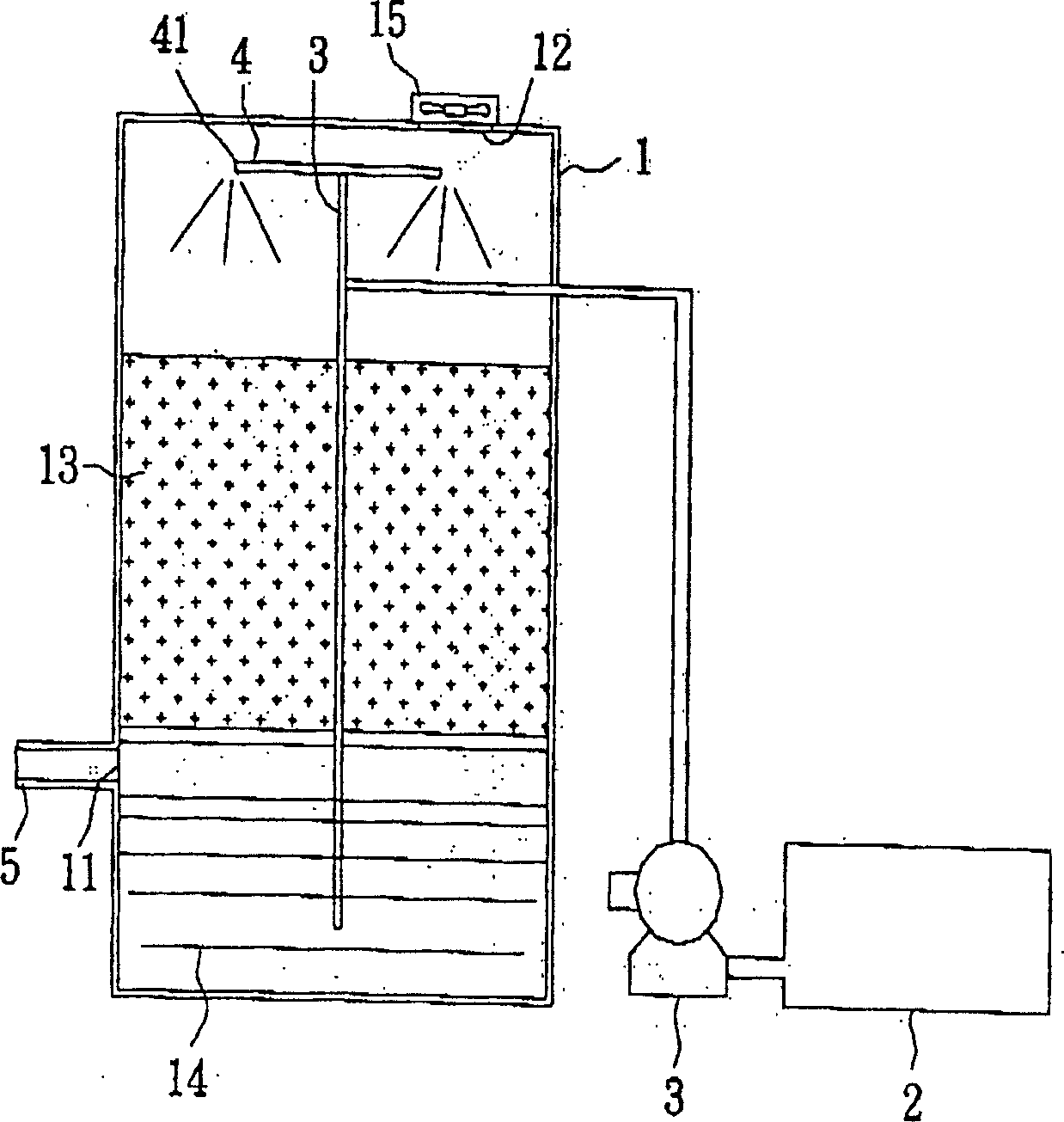
[0024] First please refer to figure 1 , is a schematic circle of the device for reducing ozone concentration in exhaust gas of the present invention. As shown in the figure, the lower end of the tank body 1 has a gas input port 11, which is connected to a pipeline 5; the upper end of the tank body 1 has a gas discharge port 12, and the gas discharge port 12 is equipped with a row of fans 15 to effectively discharge the gas; Moreover, a plurality of filler particles 13 are filled in the tank body 1 . Therefore, when the gas in the pipeline 5 is input into the tank body 1 through the gas input port 11, the gas will first pass through the gap of the filler 13, and then be discharged from the gas discharge port 12 on the tank body. On the other han...


PUM


Abstract

A process for decreasing the concentration of ozone in waste gas includes such steps as providing a water-washing device consisting of a gas inlet, a gas outlet and several slots containing filler in them, a liquid filling element for making the reducer solution flow through said filler and a storage tank connected with said liquid filling element, filling said waste gas in to the device for making it in contact with the reducer solution, and exhausting the gas from said gas outlet.

Description

technical field [0001] The invention relates to a water washing device and method, in particular to a water washing device and method suitable for reducing the concentration of ozone in waste gas. Background technique [0002] With the rapid development of Taiwan's high-tech industry, the semiconductor industry has grown faster. The semiconductor industry includes the integrated circuit industry and the optoelectronic industry, which has a great influence on the domestic economic development. However, due to the waste liquid derived from the semiconductor component manufacturing process , waste water, waste gas and other environmental issues should be highly valued. Among them, the oxide film process and the wet cleaning process of the optoelectronic semiconductor process both use high-concentration ozone (O 3 ), the system light residual ozone (O 3 ) if not properly handled, will lead to multiple industrial safety, environmental protection and personnel health hazards. ...

Claims


Application Information

Patent Timeline
12 Apr 2006
Publication
CN1757429A
IPC
B01D53/66; B01D53/78
CPC
Y02A50/20
Inventors
颜绍仪; 游生任