
Real-time flow media communication transmission system and method

A technology of communication transmission and real-time streaming, applied in transmission systems, digital transmission systems, data exchange networks, etc., can solve the problems of low server performance, high packet loss rate of terminals, and inability to use normally, so as to improve overall performance and reduce network performance. dithering effect

Inactive Publication Date: 2006-04-26
ZTE CORP
View PDF0 Cites 52 Cited by
  • Summary
  • Abstract
  • Description
  • Claims
  • Application Information

AI Technical Summary

Problems solved by technology

[0004] For example: video terminal A transmits its own video stream to video terminal B through the server. If the network condition between A and the server is good during the transmission, but due to the current heavy service load or insufficient processing capacity of video terminal B, video terminal B may end up Unable to obtain satisfactory video communication effect
[0005] 2. The transmission method adopted by the existing video communication system fails to take into account another feature of the video communication system: the terminals connected to the video communication system are not equal
[0006] The server of the video communication system serves as the service center, and all terminals communicate with other terminals through the server, but the processing capabilities of each terminal and the network connection with the server are not the same, that is to say, the terminals in the video communication system are not connected to each other. etc., for example: in a communication system, a client connected to a server through a broadband network adopts a coding method that occupies a large bandwidth, which consumes a large amount of system resources of the server and reduces the performance of the server. A good terminal has a high packet loss rate, which may not be used normally. At this time, even if the encoding method and transmission method are adjusted, the problem cannot be effectively solved.
For another example, if a system adopts a unified encoding format or transmission mode, better results cannot be obtained for terminals with strong processing capabilities and good network conditions, while terminals with weak processing capabilities and poor network conditions may not be able to work normally. use

Method used


Image

  • Real-time flow media communication transmission system and method
  • Real-time flow media communication transmission system and method
  • Real-time flow media communication transmission system and method

Examples


Embodiment Construction

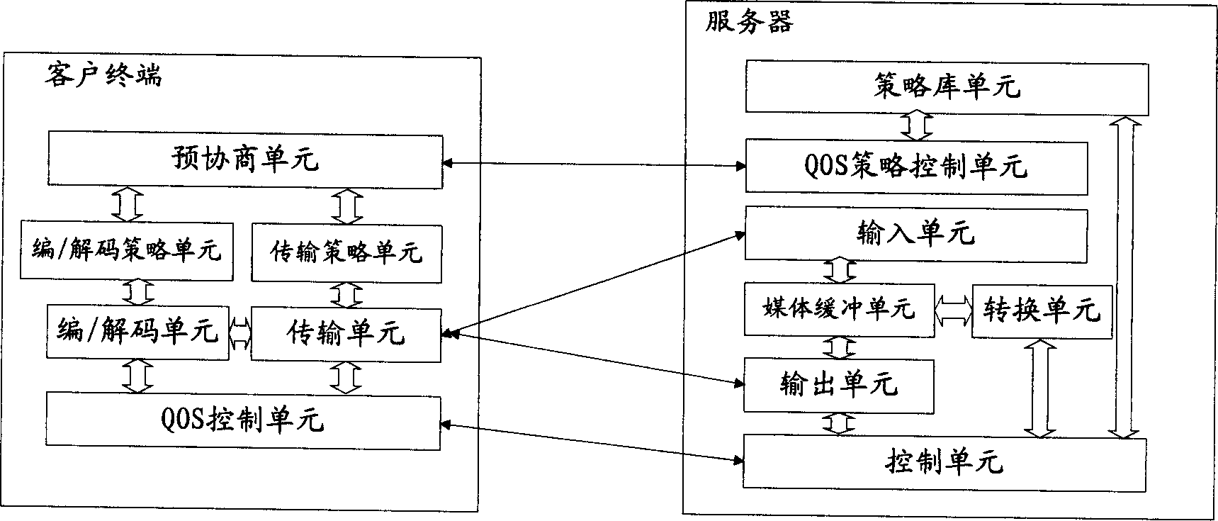
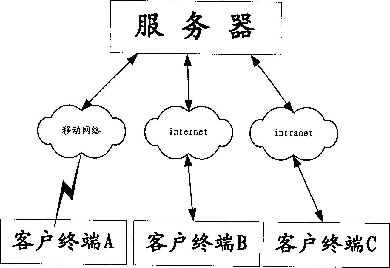
[0066] The following is attached figure 1 , 2 This embodiment is described in detail, but not as a limitation to the present invention.

[0067] Such as figure 2 As shown, the policy library unit on the server of the video communication system stores several QOS policies. The QOS policies are composed of encoding / decoding policies and transmission policies. All policies are classified according to video communication quality, bandwidth occupied during transmission, and server overhead during execution. Client terminals A, B, and C are connected to the server through the mobile network, Internet, and Intranet respectively. The processing capabilities and network conditions of the client terminals are different. Client terminal A is a mobile device with weak processing capabilities. It is connected to the server through the mobile network. The bandwidth is unlikely to be only 50k, so that client terminal A can only choose codec algorithms and transmission methods that require...


PUM


Abstract

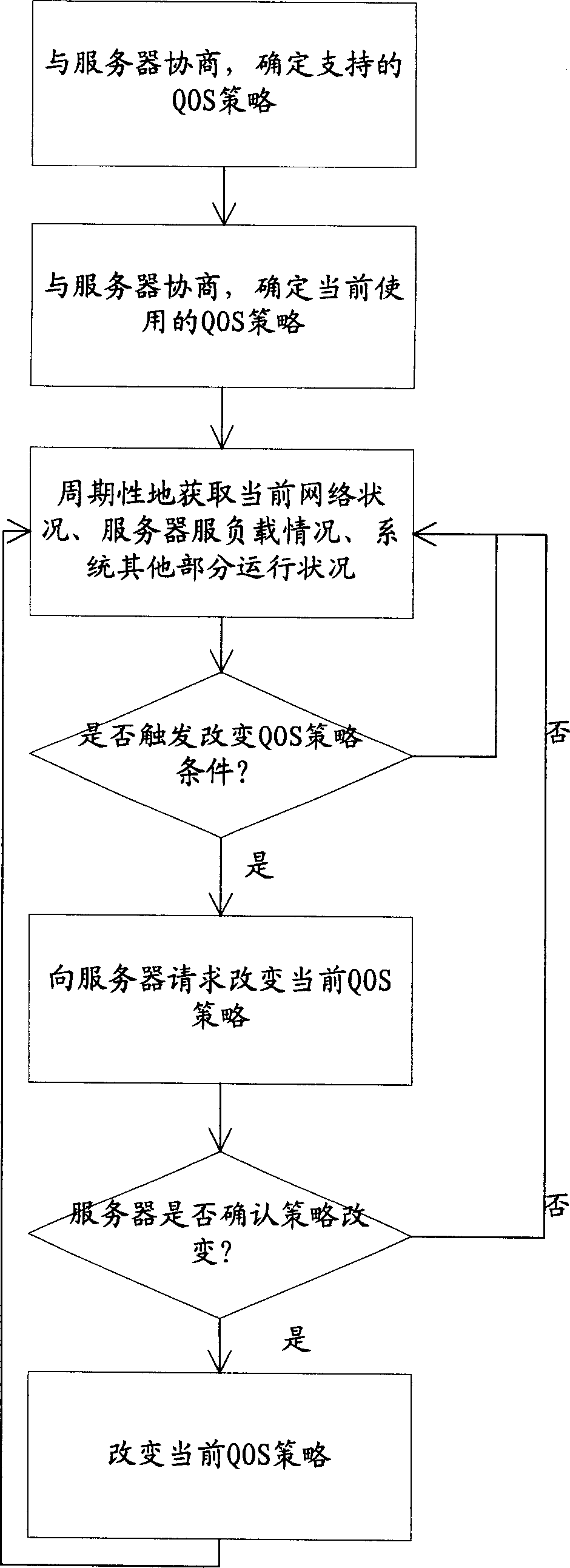
The invention provides a real-time flow media communication transmission method ,which comprises: 1. prestoring strategy to support different QOS both in server and client terminal respectively; 2. client terminal and server negotiate and determine current QOS strategy and form local strategy gradient table when client telnets; 3. server sets the conversion and transmission or client terminal according to negotiated result; 4. the client terminal and server exchange network running condition periodically to adjust QOS strategy real time. This invention comprehensive evaluates the prestored parameters, current network condition, current server load condition and objective running state to adaptive control encode and transmission means, and makes the whole system on optimal state.

Description

technical field [0001] The present invention relates to a streaming media transmission system and method, more particularly to a real-time streaming media communication transmission system and method. Background technique [0002] With the development of network technology, a new media technology emerges at the historic moment, which is streaming media technology. Streaming media refers to continuous time-based media such as audio, video or multimedia files using streaming technology in the network. Streaming media technology has been greatly used in video telephony and video conferencing systems. When network congestion occurs, data may be lost at the bottleneck router. Existing video communication systems usually use methods such as calculating the packet loss rate and comparing the data packet processing intervals at the sending and receiving ends to detect the current network status and dynamically Adapt to the current network transmission conditions by adjusting the b...

Claims


Application Information

Patent Timeline
IPC IPC(8): H04L29/06H04L12/851
Inventor 夏正勋
Owner ZTE CORP
Learn More