Semiconductor laser analyzer with portable terminal
A portable terminal and analysis system technology, applied in the field of semiconductor laser analysis system, can solve the problems of inconvenient system installation, debugging, maintenance, etc., achieve data analysis function and communication function increase, data analysis function and communication function enhancement, convenience Effects of operation and maintenance
- Summary
- Abstract
- Description
- Claims
- Application Information
AI Technical Summary
Problems solved by technology
Method used
Image

Examples
Embodiment 1
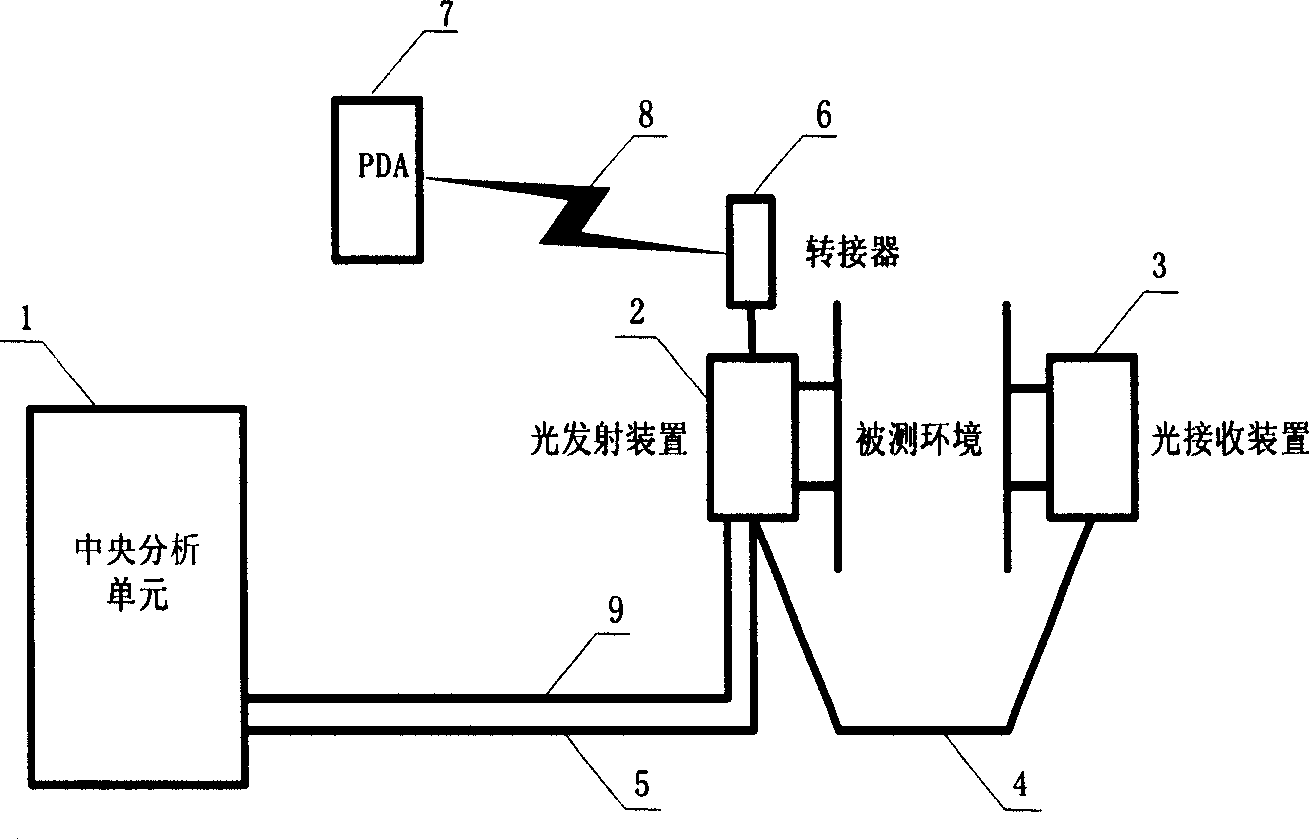
[0038] Refer to attached figure 1 , 5 , 6, 7, 8, 9, 10: the system of the present invention includes the central analysis unit 1, the light emitting device 2, the light receiving device 3, the personal digital assistant (PDA) with the external data communication interface 506 with the external data communication interface 513 ) 7 and the communication interface adapter 6 for connecting the external data communication interface 513 of the central analysis unit 1 with the external data communication interface 506 of the PDA7. The communication interface adapter 6 is installed near the measurement probe (light emitting device 2 and light receiving device 3).
[0039] The light emitting device 2 and the light receiving device 3 are installed and fixed on both sides of the chamber or pipe (such as various flue gas pipes) of the measured environment through a mechanical connection structure. The mechanical connection structure can adopt a flange structure, and the flange connection...
Embodiment 2
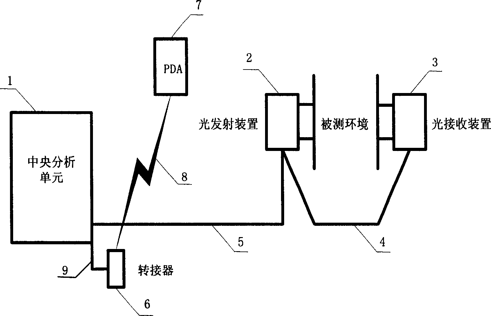
[0067] Refer to attached figure 2 , 5 , 6, 7, 8, 9, 10: the central analysis unit 1 is configured with an RS232 serial port external data communication interface 513 , and the PDA 7 is configured with a Bluetooth external data communication interface 506 . The communication interface adapter 6 is arranged in or near the central analysis unit 1 and has an RS232-Bluetooth transfer function. The communication interface 512 at one end is connected with the external data communication interface 513 of the central analysis unit 1 through the RS232 cable 9. One end is a wireless transmitting and receiving port 510 whose transmitting and receiving frequency is on the same band as that of the Bluetooth communication interface 506 of the PDA 7 , and realizes wireless communication through the free space 8 between the PDA 7 and the adapter 6 .
[0068] The remaining structures and implementation methods of this embodiment are the same as those of Embodiment 1. This embodiment can be a...
Embodiment 3
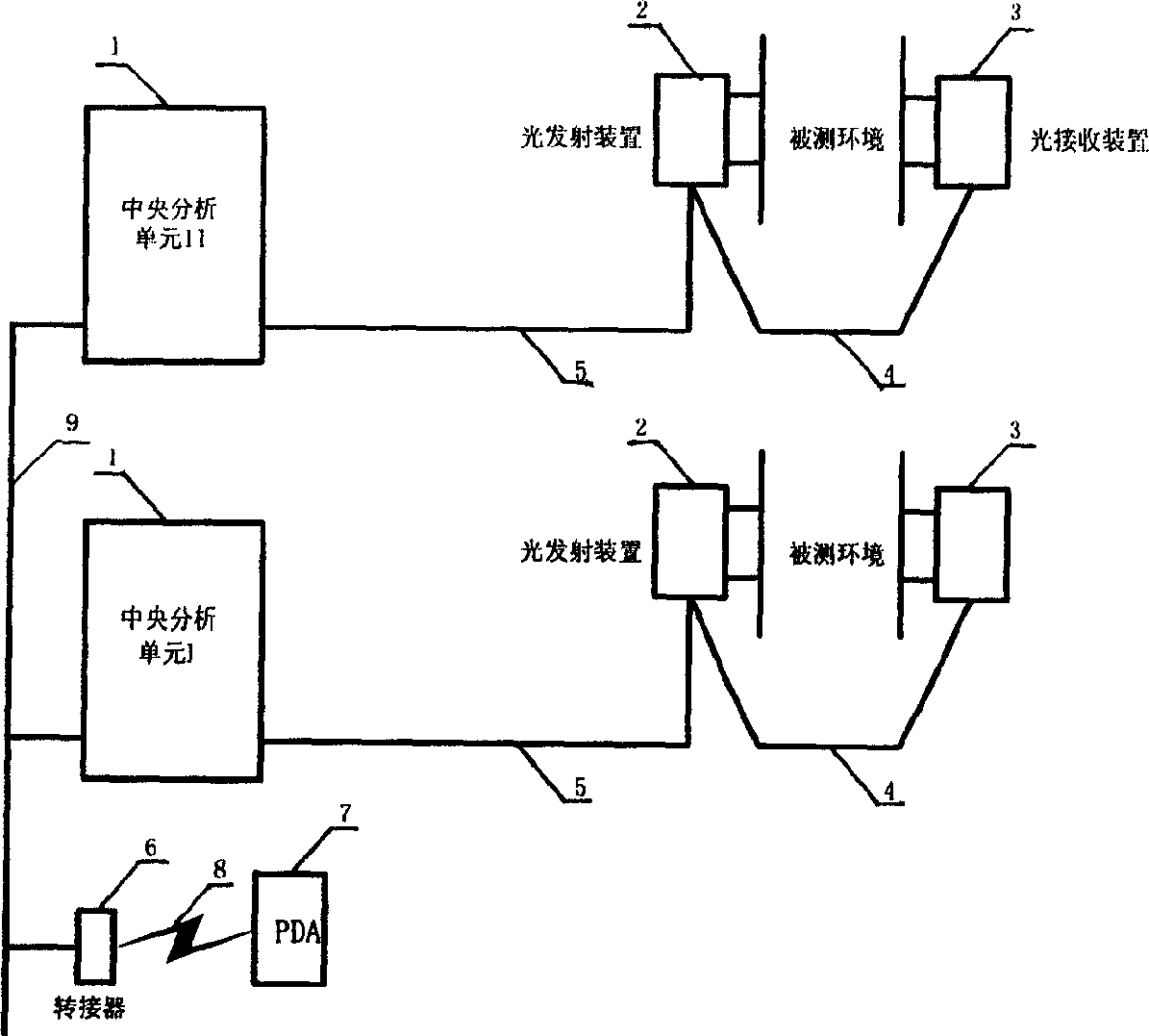
[0070] Refer to attached image 3 , 5 , 6, 7, 8, 9, 10: both the central analysis unit I and the central analysis unit II are equipped with an RS485 serial port external data communication interface 513, and the PDA 7 is equipped with a Bluetooth external data communication interface 506. The communication interface adapter 6 can be located in any central analysis unit or an independent device, and has the RS485-Bluetooth transfer function, and the communication interface 512 at one end communicates with the central analysis unit I and the central analysis unit II through the RS485 cable 9 form a communication network. The other end is a wireless transmitting and receiving port 510, whose transmitting and receiving frequency is on the same band as that of the Bluetooth communication interface 506 of the PDA 7, and realizes wireless communication through the free space 8 between the PDA 7 and the adapter 6. There may be more central analysis units participating in the network...
PUM
 Abstract
Description
Claims
Application Information
 - Generate Ideas
- Intellectual Property
- Life Sciences
- Materials
- Tech Scout
- Unparalleled Data Quality
- Higher Quality Content
- 60% Fewer Hallucinations
Browse by: Latest US Patents, China's latest patents, Technical Efficacy Thesaurus, Application Domain, Technology Topic, Popular Technical Reports.
© 2025 PatSnap. All rights reserved.Legal|Privacy policy|Modern Slavery Act Transparency Statement|Sitemap|About US| Contact US: help@patsnap.com