Photo thermal driving micro motor

A micro-motor and photothermal technology, which is applied to motors, generators/motors, and electrical components that apply thermal effects, can solve problems such as lack of mechanisms and methods for similar micro-miniature photothermal drive motors, and achieve a small step distance. , easy to miniaturize, structure independent effect

Inactive Publication Date: 2006-05-24
ZHEJIANG UNIV
View PDF0 Cites 15 Cited by
  • Summary
  • Abstract
  • Description
  • Claims
  • Application Information

AI Technical Summary

Problems solved by technology

However, the research on the interaction between laser and solid matter at the micro / nano scale, especially the basic research on the application of light-induced thermal expansion and its driving mechanism, is still lacking. Literature reports on mechanism and method studies

Method used


Image

  • Photo thermal driving micro motor
  • Photo thermal driving micro motor
  • Photo thermal driving micro motor

Examples


Embodiment Construction

[0011] The invention adopts a research method combining laser technology, micro / nano technology and micro-special motor technology. The micro / nano-scale photothermal effect is used to cause thermal expansion of solid materials to directly drive the motor.

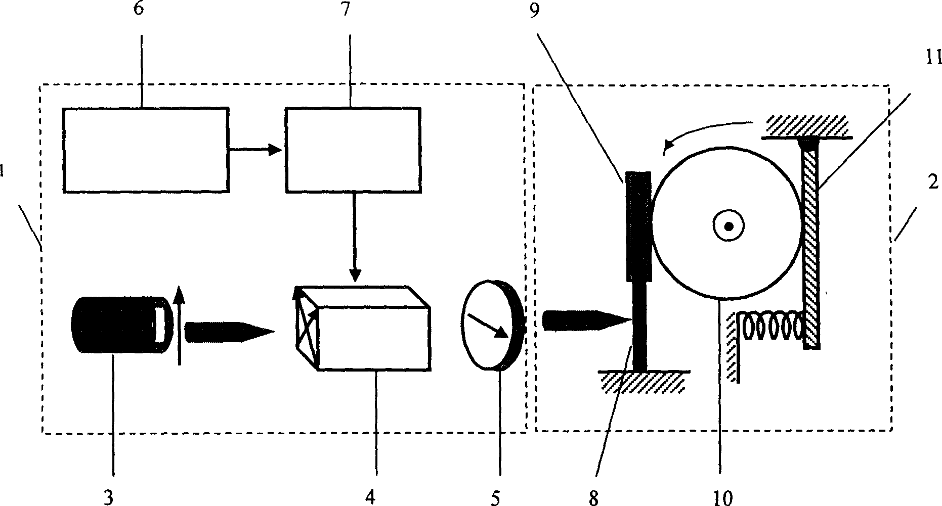
[0012] figure 1 As shown, the photothermal drive micromotor has a pulse light source system 1 and a rotation system 2. The pulse light source system 1 has a laser 3, an electro-optic crystal 4, and a polarizing disk 5 arranged in sequence. The electro-optic crystal 4 is composed of a pulse signal generation module 6 and an amplification circuit 7. Control, the rotation system 2 has an expansion arm 8, a friction plate 9, a coaxial rotor 10 and a pressure spring 11. One end of the expansion arm 8 is fixed, and the other end is bonded to the friction plate 9. One end of the pressure spring 11 is fixed, and the other end is fixed. It is connected with a spring, and the rotor 10 is connected with the pressure spring 11 and the...


PUM


Abstract

The mocro motor includes a system of pulsed light source and a rotation system. The system of pulsed light source possesses laser, electrooptic crystal, polarization disk. The electrooptic crystal is controlled by pulsed signal generation module and amplification loop. The rotation system possesses an expanding arm, friction plate, coaxial rotor, and a piece of compression spring. One end of the expanding arm is fixed, and the other end is pasted to the friction plate. One end of the piece of compression spring is fixed, and the other end is connected to a spring. The rotor is connected to the piece of compression spring, and the friction plate. Advantages are: small output step pitch, high speed, driven by laser directly, no read wire required, microminiature, possible to be placed in enclosure space (such as vacuum cavity), and remote controllable.

Description

technical field [0001] The invention relates to a light-thermal driven micro-motor, which is used for high-speed and small-step driving in the field of micro-nano technology. Background technique [0002] In recent years, an important trend in the development of science and technology is to move rapidly towards high speed, large capacity and miniaturization. Among them, the development of micro / nano technology, micro mechanical technology, optics and optoelectronic technology is the main representative. In many special fields, it is necessary to use a motor (or motor) with special performance as a power source and a motion source. For example, motors used for precise driving and positioning of components in optical and precision mechanical systems require high speed, fast response, and miniaturization as much as possible; motors used in spacecraft and space satellites require both large torque and high efficiency , and require light weight, small size, and long life; in th...

Claims


Application Information

Patent Timeline
Patent Type & Authority Applications(China)
IPC IPC(8): H02N10/00
Inventor 张冬仙何玉琳章海军
Owner ZHEJIANG UNIV
Why Eureka
Try Eureka