Methanol dynamic device and work done method by methanol pyrolysis

A power plant, methanol cracking technology, applied to engine components, combustion engines, machines/engines, etc., to achieve the effect of improving thermal efficiency and reducing compression power consumption

Inactive Publication Date: 2006-05-31
INST OF ENGINEERING THERMOPHYSICS - CHINESE ACAD OF SCI
View PDF1 Cites 6 Cited by
  • Summary
  • Abstract
  • Description
  • Claims
  • Application Information

AI Technical Summary

Problems solved by technology

[0003] Chinese invention patent 85109487.2 utilizes engine waste heat to crack methanol and then blends it with gasoline or diesel, which has remarkable energy-saving and environmental protection effects, but its cycle thermal efficiency can still be further improved

Method used


Image

  • Methanol dynamic device and work done method by methanol pyrolysis

Examples


Embodiment Construction

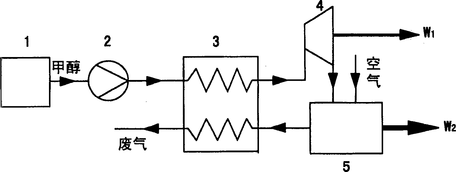
[0022] Combine below figure 1 Describe in detail the details and working conditions of the specific device proposed according to the present invention.

[0023] Such as figure 1 As shown, the methanol power plant of the present invention is composed of a methanol tank 1, a methanol pump 2, a heat exchanger / cracker 3, a turbine 4 and an internal combustion engine 5. Catalyst is accommodated in heat exchanger / cracker 3, such as supported molten salt catalyst CuCl-KCl / SiO 2 . Wherein the internal combustion engine 5 is provided with an air inlet for introducing air.

[0024] Methanol is stored in the methanol tank 1, and the liquid methanol from the methanol tank 1 is pressurized by the methanol pump 2 to a corresponding pressure and then enters the heat exchange / cracker 3, where the waste heat from the exhaust of the internal combustion engine 5 is received in the heat exchange / cracker 3. Vaporization and cracking under the action of catalyst. The cracked mixed gas enters t...


PUM


Abstract

A methanol power engine comprises methanol tank, pump, heat exchanger/cracking unit, turbine and engine. The heat exchanger/cracking unit is linked to the pump, turbine and the engine. The turbine is linked to the engine. The exhaust from the engine is used to heat methanol for cracking. After compressed, methanol flows into the heat exchanger/cracking unit and cracks with the heat from the engine exhaust. The cracked gas moves the turbine then the engine. The exhaust gas is exhaled after the heat exchanger. Compared with liquid fuel, less CO and hydrocarbons are exhausted. NOx content could also be decreased by ultra amount of air.

Description

technical field [0001] The invention relates to an engine, in particular to a methanol power plant. The invention also relates to a method of utilizing methanol cracking to perform work. Background technique [0002] With the aggravation of energy crisis and environmental pollution, methanol is attracting attention as an alternative fuel. However, mixed combustion of methanol or direct combustion of methanol leads to a decrease in engine power and excessive aldol emissions. Cracking methanol into hydrogen-rich mixture and burning it into the engine can not only improve efficiency, but also reduce pollution. It is an ideal way to use methanol fuel. [0003] Chinese invention patent 85109487.2 utilizes waste heat from the engine to crack methanol and then blends it with gasoline or diesel. Its energy-saving and environmental protection effects are remarkable, but its cycle heat efficiency can still be further improved. Contents of the invention [0004] The main purpose o...

Claims


Application Information

Patent Timeline
Patent Type & Authority Applications(China)
IPC IPC(8): F02B43/10
CPCY02T10/30
Inventor 曲延涛张国强
Owner INST OF ENGINEERING THERMOPHYSICS - CHINESE ACAD OF SCI
Why Eureka
Try Eureka