Brushless DC motor and its current converting and controlling method thereof

A technology of brushed DC motor and DC bus, which is applied in the direction of electronically commutated motor control, DC commutator, excitation or armature current control, etc. It can solve the problems of large switching loss and insufficient working conditions

Inactive Publication Date: 2006-06-14
李荟敏
View PDF0 Cites 22 Cited by
  • Summary
  • Abstract
  • Description
  • Claims
  • Application Information

AI Technical Summary

Problems solved by technology

However, the switching element of the commutator frequency converter of the commutator-free DC motor that uses the pulse width modulation technology to drive the three-phase windings needs to have the ability to turn off, and the working conditions are not good enough, which brings about the defect of large switching loss. It is still improving and needs further improvement, such as adopting more complex soft switching technology, etc.

Method used


Image

  • Brushless DC motor and its current converting and controlling method thereof
  • Brushless DC motor and its current converting and controlling method thereof
  • Brushless DC motor and its current converting and controlling method thereof

Examples


Embodiment Construction

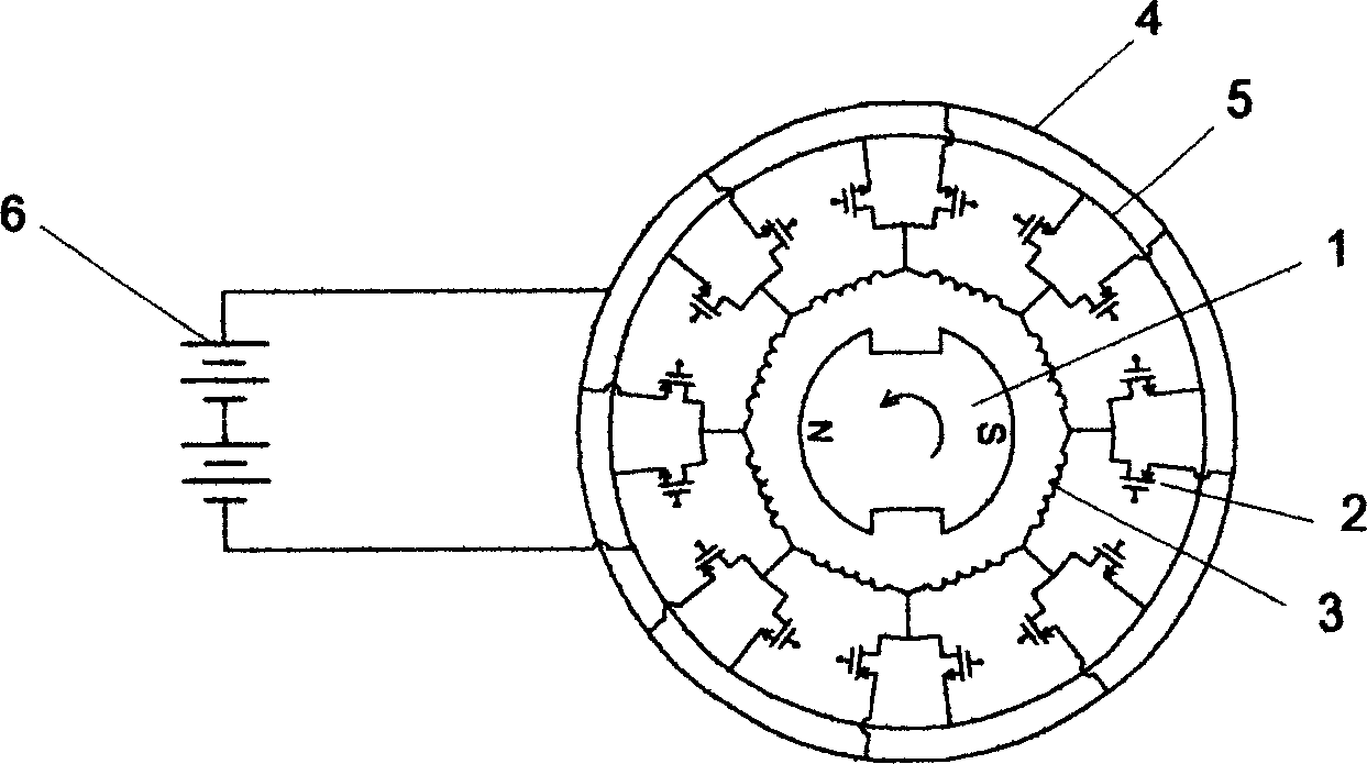
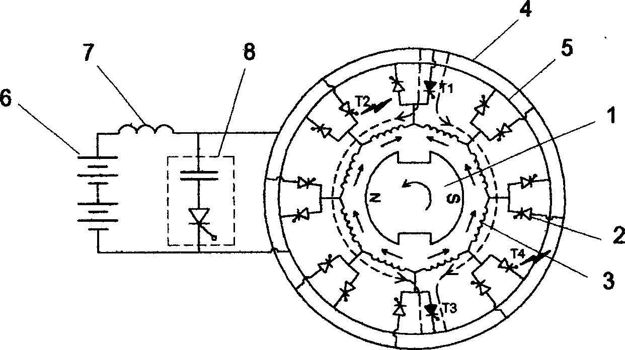
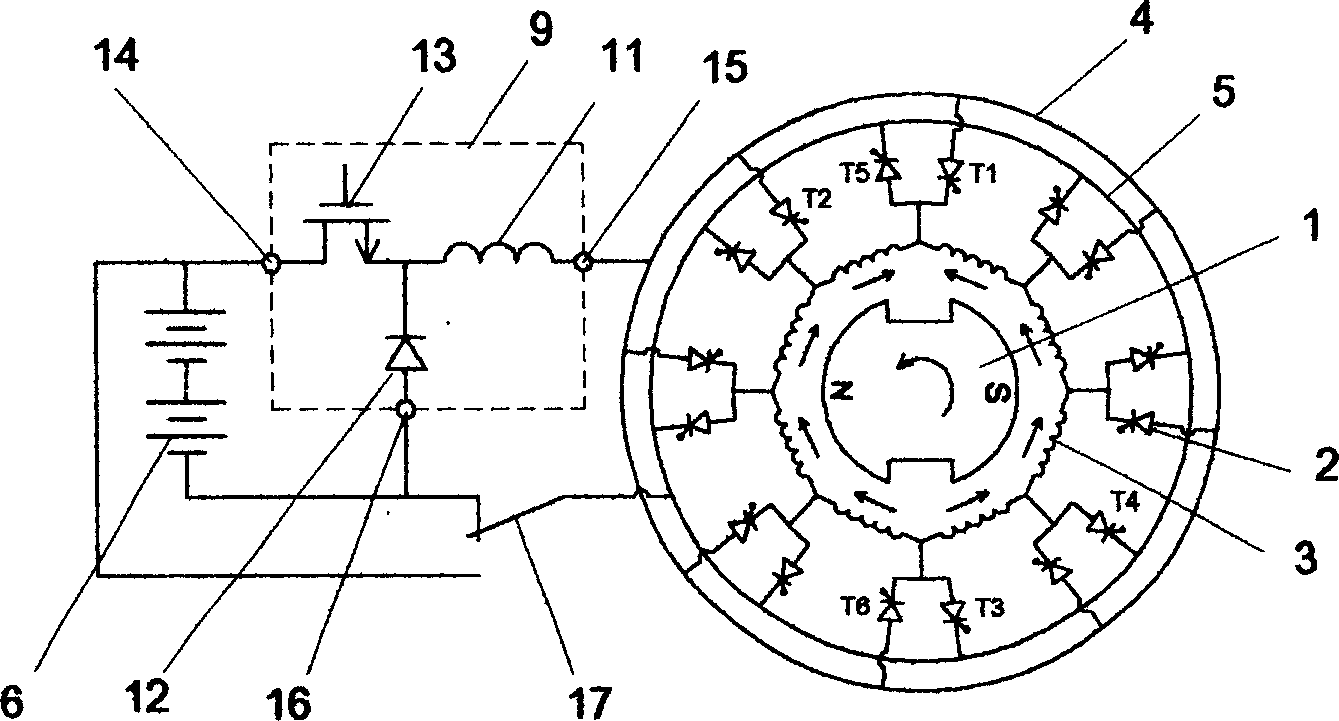
[0019] like figure 1 As shown, 1 is the magnetic pole rotor, which can be permanent magnet or excitation; 2 is the power electronic switching device, which can be a thyristor, a turn-off thyristor, or a power FET or an insulated gate field effect Transistors, etc.; 3 is the armature winding, which is the same or similar to ordinary DC motors; 4 is the positive DC bus; 5 is the negative DC bus; 6 is the DC power supply. Other electromagnetic structures are the same as those of various existing DC motors, and will not be described in detail. figure 1 The shown armature winding and its connection topology with power electronic switching devices have constituted a complete commutation structure, which can completely imitate the commutation of a mechanical commutator DC motor at a geometric neutral point or a physical neutral point , to obtain ideal DC motor operating characteristics. However, power electronic switching devices need to have the ability to turn off autonomously, a...


PUM


Abstract

This invention discloses a brushless DC motor and its current conversion and control method used in the field needing regulating the speed of the work or the field not needing regulating the speed yet it is higher than 3000t / m including multiple winding elements with their head and tail elements connected to a closed loop and power electronic switches connected with it, other magnetic structure is the same with the DC motor of a machinery commutator. When it works normally, it utilizes the armature potential to turn off a necessary switch, such as using a thyristor to finish the commutation and when the switch is turned on, the forward voltage born by the switch is far smaller than the supply voltage and the supply control circuit is used to control the operation of the conversion when it starts or operates at low speed and a reversal speed control system can be set up combining with a thyristor commutation device.

Description

technical field [0001] The invention discloses a brushless direct current motor and its commutation and control method, which is suitable for occasions requiring speed regulation operation or occasions where the working speed is higher than 3000 r / min although the speed regulation is not required. For example, various electric transmission vehicles include but are not limited to electric transmission wheeled vehicles or tracked vehicles such as tanks, armored vehicles and tractors, electric transmission vehicles, electric vehicles, electric transmission rail diesel locomotives and electric locomotives, subway or light rail electric vehicles, Electric drive ships, submarines; and various equipment including but not limited to industrial and mining fans, pump stations and various refrigeration or metallurgical chemical industry equipment including but not limited to compressors, rolling mills and various material conveying machinery; various mechanical processing Equipment inclu...

Claims


Application Information

Patent Timeline
Patent Type & Authority Applications(China)
IPC IPC(8): H02K29/00H02K23/30H02K23/32H02K23/34H02P7/06
CPCH02K3/28H02K11/33H02P6/182H02P21/0089
Inventor 李荟敏
Owner 李荟敏
Why Eureka
Try Eureka