Biomass combustion device with low NOx emission and combustion method thereof

The technology of a combustion device and combustion method is applied in the direction of solid fuel combustion, combustion equipment, lighting and heating equipment, etc. It can solve the problems of poor burnout degree, open-air combustion pollution, and high volatile biomass, so as to reduce black emission High smoke and CO emissions, improved combustion efficiency, and reduced rapid combustion effects

Inactive Publication Date: 2006-06-21
INST OF PROCESS ENG CHINESE ACAD OF SCI
View PDF1 Cites 17 Cited by
  • Summary
  • Abstract
  • Description
  • Claims
  • Application Information

AI Technical Summary

Problems solved by technology

my country is rich in biomass energy, among which the density of agricultural waste is small, the stacking volume is large, the open burning pollution is serious, and the safety hazard is great. Therefore, people have developed a variety of biomass burning and utilization methods, but due to the high volatile content of biomass, coke Combustion and volatile combus

Method used


Image

  • Biomass combustion device with low NOx emission and combustion method thereof
  • Biomass combustion device with low NOx emission and combustion method thereof
  • Biomass combustion device with low NOx emission and combustion method thereof

Examples


Embodiment 1

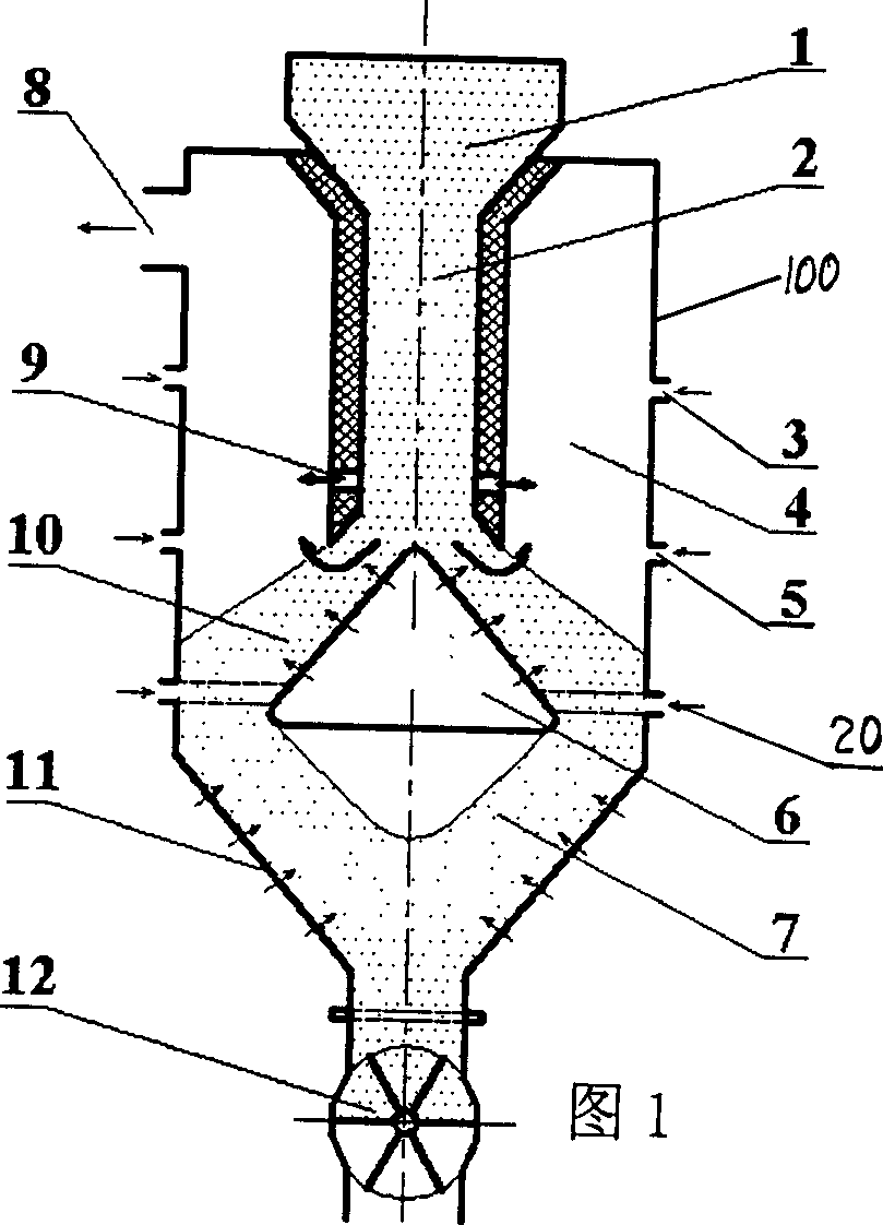
[0032] FIG. 1 is a schematic diagram of the structure of Embodiment 1. FIG.

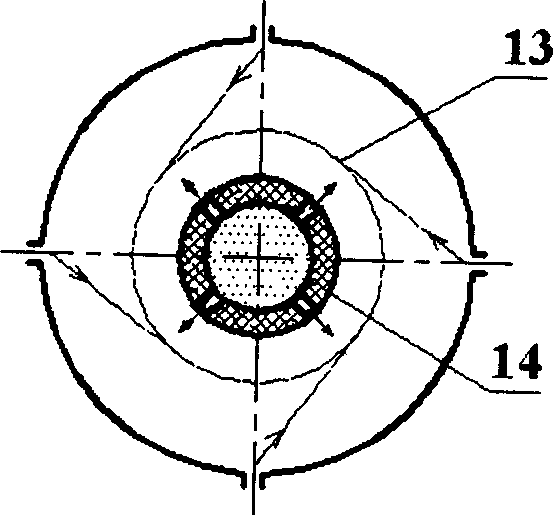
[0033] The combustion furnace 100 of Embodiment 1 is a straight cylinder, the cylindrical pyrolysis chamber 2 is located in the middle of the furnace, and the lower part is an inverted cone grate 11 connected to a rotary valve type slag tapping device 12. During the combustion process, the feed, slag removal and combustion speed of the biomass fuel are all controlled by the rotary valve type slagging device 12 at the lower part of the furnace. Biomass fuel enters the pyrolysis chamber 2 located in the center of the furnace from the hopper 1 at the upper part of the furnace, and is quickly heated and precipitated volatiles under the action of the heat in the furnace. A part of the separated volatiles enters the combustion chamber 4 through the communication port 9 to burn, and the other part The volatiles along with the coke after fuel pyrolysis enter the reduction zone 10 for combustion along the cone-sh...

Embodiment 2

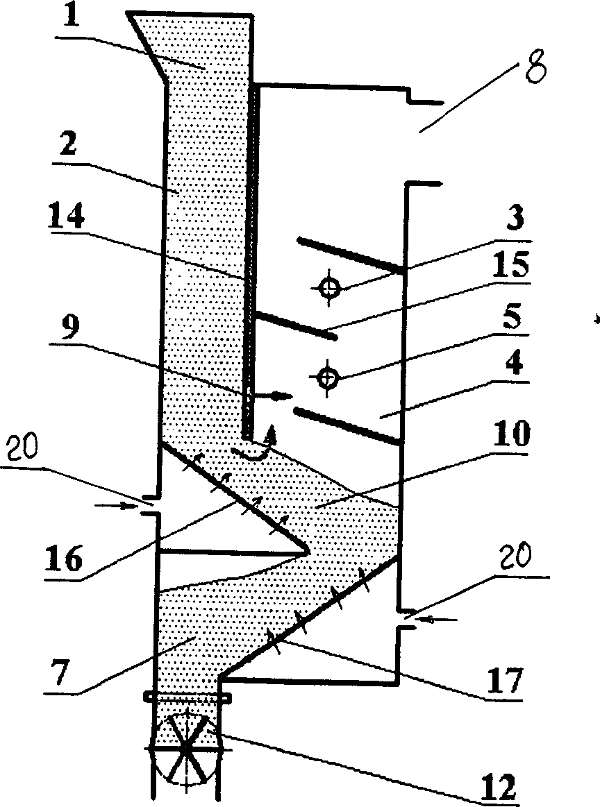
[0035] Attached image 3 It is a schematic diagram of the structure of Example 2.

[0036] The cross section of the furnace hearth of Embodiment 2 is rectangular, and the upper part of the furnace hearth is divided into the pyrolysis chamber 2 and the combustion chamber 4 by the partition plate 14. Two-layer inclined grate such as image 3In the arrangement shown, the feed, slag removal and combustion speed of the biomass fuel are all controlled by the screw conveyor 12 at the lower part of the furnace. Biomass fuel enters the pyrolysis chamber 2 from the hopper 1 in the upper part of the furnace, and is quickly heated to separate volatiles under the action of the heat in the furnace. Part of the separated volatiles enters the combustion chamber 4 through the communication port 9 and burns, and the other part of the volatiles follows the fuel. The pyrolyzed coke enters the reduction zone 10 along the upper inclined grate 16 and burns. In the reduction zone, the coke and volatile mat...


PUM


Abstract

This invention relates to biomass low NOx burst device and its method, wherein, the device comprise the following parts: stand burst furnace with smoke channel exit with its inside isolation board as bottom heat chamber and burst chamber and connection hole; the material bin on the heat chamber; inclined furnace row and rotation reside device down the burst chamber; reducing zone and burst zone inside the burst chamber located with once, secondary and third wind-in mouth. The method combines the biomass characteristics of fully burst and coke burst to form different burst environment to reduce black smoke.

Description

Invention field [0001] The invention relates to a biomass combustion device and a combustion method, in particular to a high-efficiency combustion device that can effectively reduce soot, nitrogen oxides (NOx) and carbon monoxide (CO) emitted by biomass combustion and improve biomass combustion and utilization efficiency And the method of combustion. Background technique [0002] With the increasing scarcity of fossil energy, the development and utilization of biomass energy, the fourth largest energy source, has attracted much attention. China is rich in biomass energy. Among them, the density of agricultural waste is small, the stacking volume is large, the open burning pollution is serious, and the safety hazard is high. For this reason, people have developed a variety of biomass combustion and utilization methods. However, due to the high volatile content of biomass, coke Combustion and volatile matter combustion are not synchronized, the degree of burnout is poor, and the bl...

Claims


Application Information

Patent Timeline
IPC IPC(8): F23B10/02F23B30/00
Inventor 董利宋文立高士秋何京东李静海
Owner INST OF PROCESS ENG CHINESE ACAD OF SCI
Why Eureka
Try Eureka