
Force control method for lap surface control of stressed lap and equipment thereof

A control method and technology for controlling equipment, which are used in grinding/polishing equipment, optical surface grinders, metal processing equipment, etc., can solve the problems of large volume, slow dynamic response, and high equipment cost, and achieve simplified mechanical structure and simplified circuit structure. , the effect of improving the response speed

Inactive Publication Date: 2006-07-12
NANJING INST OF ASTRONOMICAL OPTICS & TECH NAT ASTRONOMICAL OBSE
View PDF0 Cites 9 Cited by
  • Summary
  • Abstract
  • Description
  • Claims
  • Application Information

AI Technical Summary

Problems solved by technology

In order to overcome the shortcomings of the traditional technology, such as the low rotational speed of the active polishing disc, the slow dynamic response of the active polishing disc surface shape control, the complex actuator control system, large volume, heavy weight, and high equipment cost, etc.

Method used

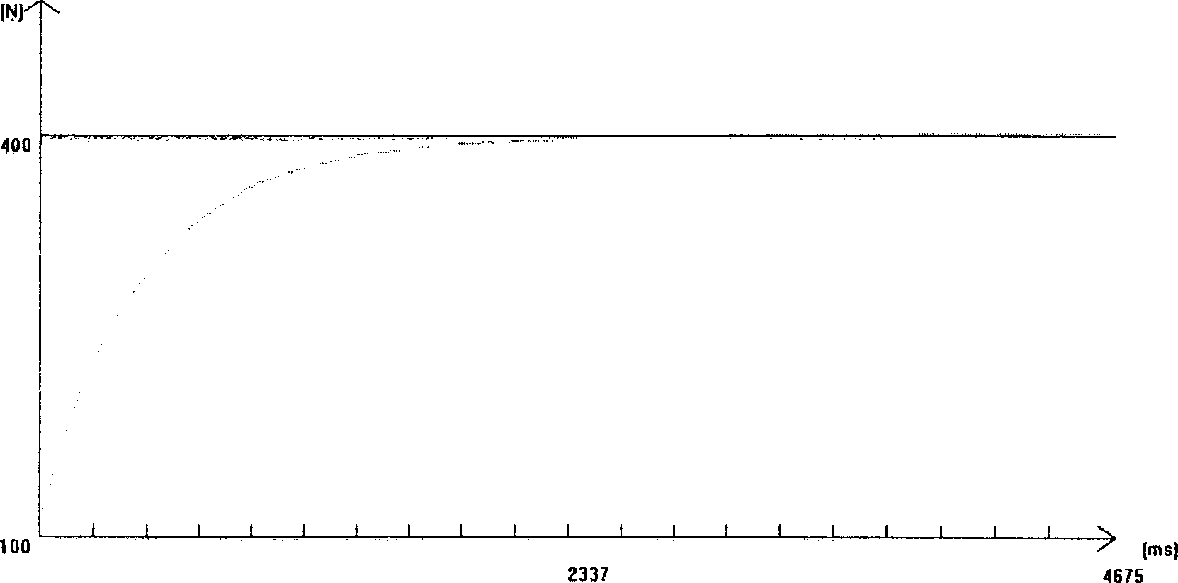
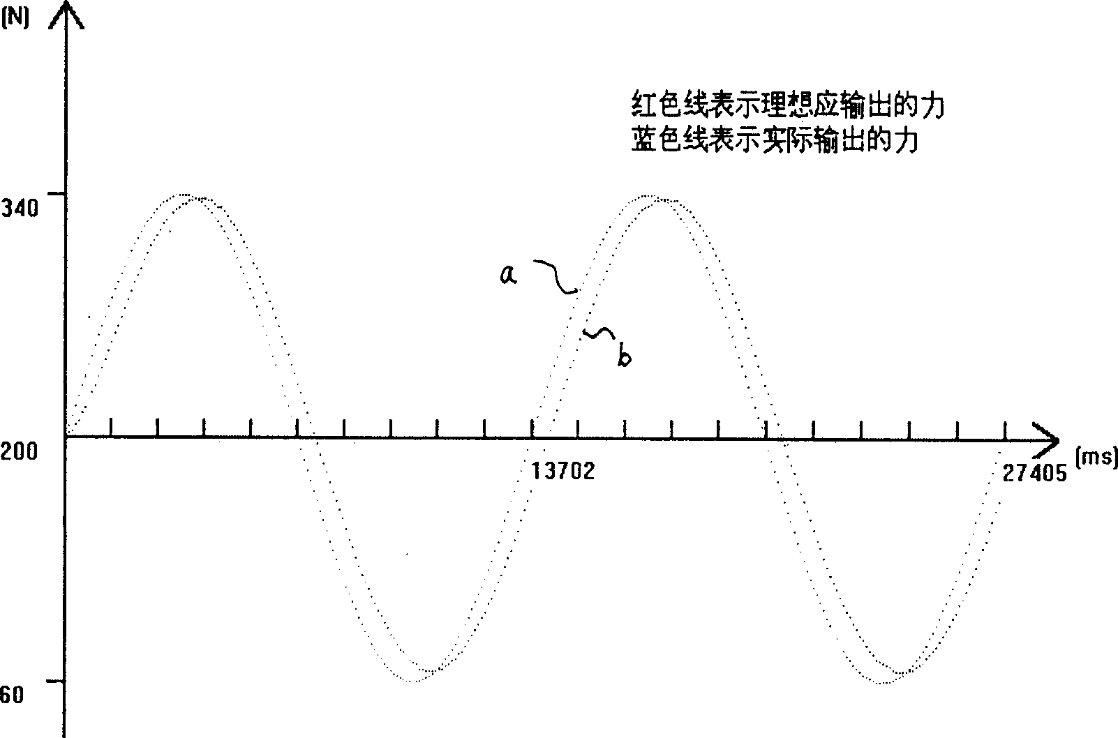
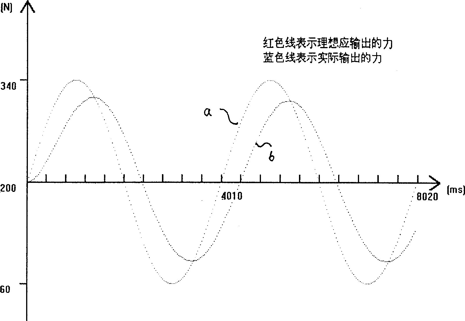

Image

  • Force control method for lap surface control of stressed lap and equipment thereof
  • Force control method for lap surface control of stressed lap and equipment thereof
  • Force control method for lap surface control of stressed lap and equipment thereof

Examples


Embodiment 1

[0063] For the hardware structure of the force actuator controller, refer to Figure 7 : the main shaft of the control motor 1 is connected with a screw rod respectively, the nut on the screw rod is connected with the steel wire rope 4 through the lever 3, and the steel wire rope 4 is fixedly connected with the fixed point on the back side of the active polishing disc; the structure of the described force actuator controller is: each One end of the wire rope is respectively provided with tension sensors 5 . Among the figure, 2 is a motor seat, and 6 is a regulator.

[0064] The specific details of the force actuator hardware are: the single-chip microcomputer selects the P89LPC938 of PHILPS Company, which adopts a high-performance processor structure, and the instruction execution time only needs 2 to 4 clock cycles, which is 6 times that of the standard 80C51 device; and integrates 8 A 10-bit A / D converter and a PWM port are provided, so that no additional A / D chip is needed...


PUM


Abstract

The invention relates to a method for controlling the force when actively burnishing the disc. It comprises that: the computer transfers the data and control instruction to the single chip; the single chip control the drawing motor to rotate the ball lead screw and the nut pushes the lever to frap steel wire; the pull sensor measures the tension force of steel wire; the measured result is transferred to single chip; at the same time, the current signal of control motor is feedback to the single chip; the single chip processes PID calculation via power amplifier to be transferred to control motor to regulate rotation speed to adjust the pull of steel wire. Since said steel wire can continuously change the shape of active burnishing surface to keep the same with adhesive part of burnished optical mirror face. The invention also provides a relative device. Since it uses a pull ring-current ring control system while integrates the computer signal process, motor driving, and the process of pull sensor into one circuit to simplify the circuit structure, the invention has small volume, lighter load and quick dynamic response.

Description

technical field [0001] The invention relates to a control technology for astronomical optical processing, in particular to a force control method for active polishing disk surface shape control. The structure of the active polishing disk can be changed by adopting the method, and the invention also relates to equipment using the method: the active polishing disk. Background technique [0002] In large-scale high-precision optical systems, large-diameter aspheric or off-axis aspheric optical mirrors are often required. Since the curvature radii of each point of the aspheric surface are different, even at the same point, the curvature in different directions is also different. Therefore, Processing aspheric surfaces cannot use larger grinding tools like spherical processing. The traditional method of grinding the aspheric mirror surface with a small tool controlled by hand or computer is faced with problems such as high-frequency cutting, low precision, and long processing cy...

Claims


Application Information

Patent Timeline
Patent Type & Authority Applications(China)
IPC IPC(8): B24B13/00B24B13/06
Inventor 李颖汪达兴
Owner NANJING INST OF ASTRONOMICAL OPTICS & TECH NAT ASTRONOMICAL OBSE
Learn More