Electro-optical modulating method and device for transmission light based on tri-step electro-optical materials

An electro-optic modulation and electro-optic material technology, applied in electromagnetic wave transmission systems, transmission systems, optics, etc., can solve the problems of instability of electro-optic organic polymers, affecting the modulation effect, reducing electro-optic coefficients, etc., to avoid thermal stability and relaxation. Henan, low cost, low driving power

Inactive Publication Date: 2006-08-16
SHANGHAI JIAO TONG UNIV
View PDF0 Cites 8 Cited by
  • Summary
  • Abstract
  • Description
  • Claims
  • Application Information

AI Technical Summary

Problems solved by technology

However, there are some problems in the use of linear electro-optic effect: ① the polarized electro-optic organic polymer is unstable, the relaxation of the chromophore is unavoidable, and the electro-optic coefficient will decrease, thereby affecting the modulation effect; ② due to the linearity of the material The electro-optic coefficient is the characteristic of the material itself. To improve the electro-optic coefficient, there is only one way to find a material with a large electro-optic coefficient.

Method used


Image

  • Electro-optical modulating method and device for transmission light based on tri-step electro-optical materials
  • Electro-optical modulating method and device for transmission light based on tri-step electro-optical materials
  • Electro-optical modulating method and device for transmission light based on tri-step electro-optical materials

Examples


Embodiment Construction

[0016] The technical solution of the present invention will be further described below in conjunction with the accompanying drawings.

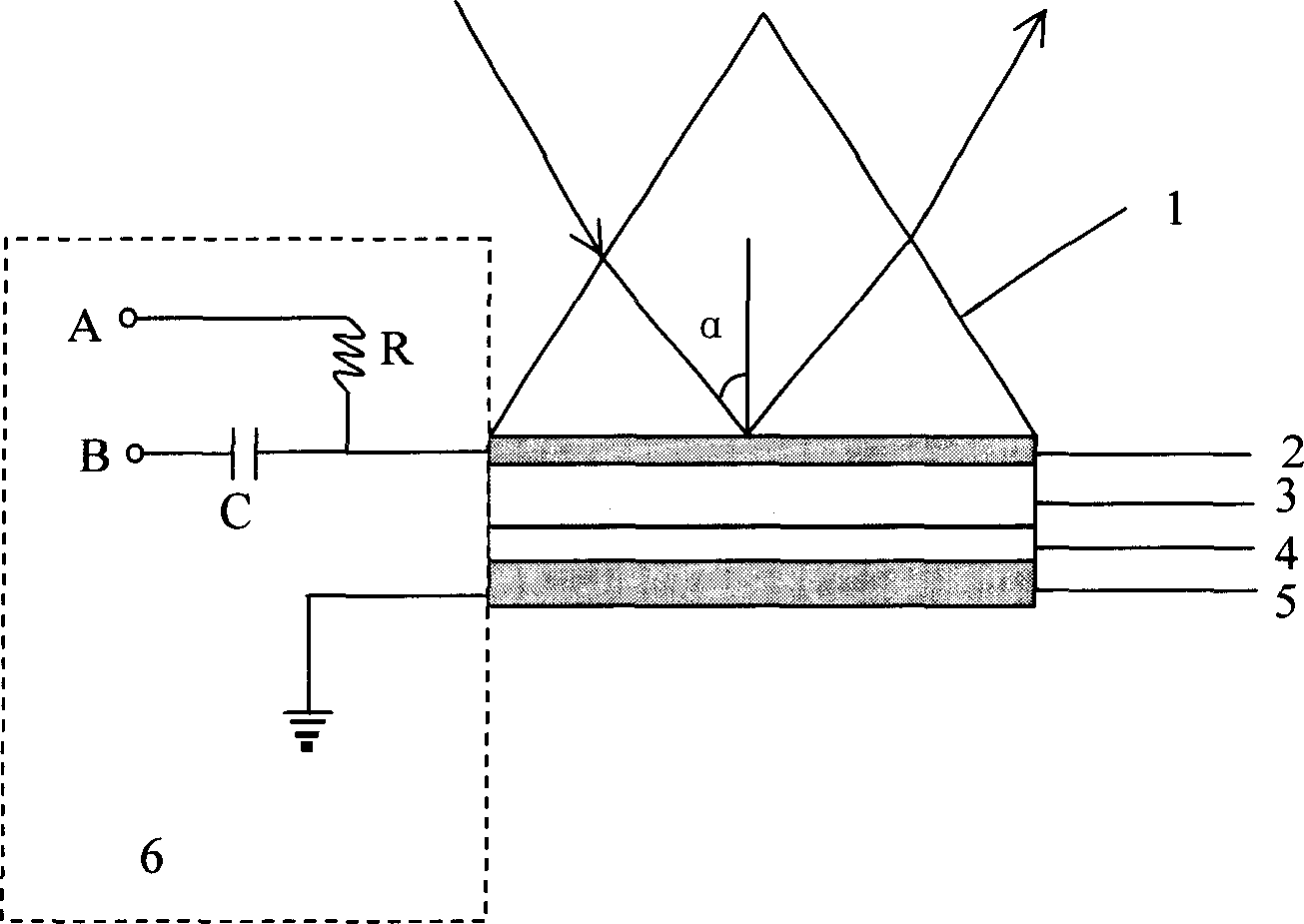
[0017] The device structure of the present invention is as figure 1 As shown, including the modulator and the input matching circuit 6, the composition of the modulator includes five layers, which are as follows from top to bottom: coupling prism 1, metal upper electrode 2, third-order organic polymer waveguide layer 3, and isolation layer 4 and metal lower electrode 5 . The matching circuit is composed of a protection resistor R and a coupling capacitor C. The DC bias terminal A of the input matching circuit 6 is connected to the upper metal electrode 2 through the protection resistor R, and the modulation signal input terminal B is connected to the upper electrode 2 through the coupling capacitor C. The input matching The ground wire of the circuit is connected to the lower electrode 5 of the modulator.

[0018] The preparation process of ...


PUM


Abstract

A device for carrying out electro optical modulation on transmission light based on third order electro optical material consists of coupled prism, metal top electrode, third order organic polymer guide wave layer, modulator formed by isolation layer and metal bottom electrode, and input matching circuit .It is featured as exerting a larger DC bias voltage and a smaller modulation input signal simultaneously on third order organic polymer guide wave layer through input matching circuit to change refractivity of said guide wave layer and so as to change reflectivity at operation angle for realizing modulation on intensity reflection light .

Description

technical field [0001] The invention relates to a method and device for electro-optic modulation of transmitted light based on a third-order electro-optical material. The principle of attenuated total reflection is adopted, and the property of the outgoing light intensity being sensitive to the upper or lower edge of the attenuated total reflection spectrum is used to control the transmitted light. Intensity modulation belongs to the fields of optoelectronic communication and optical information processing. Background technique [0002] In the field of optoelectronic communication transmission and optical information processing, it is necessary to load external electrical signals onto the transmission carrier—light waves to realize optical transmission of signals, and the device that realizes the signal loading function is the modulator. According to the different modulation principles, there are electro-optic modulation, acousto-optic modulation, magneto-optic modulation, e...

Claims


Application Information

Patent Timeline
IPC IPC(8): G02F1/065G09G3/00H04B10/00H04B10/516
Inventor 周见红曹庄琪邓晓旭郑湘沈启舜
Owner SHANGHAI JIAO TONG UNIV
Why Eureka
Try Eureka