Microwave power distributor with multiple power distributing ratios

A technology of microwave power splitter and distribution ratio, which is applied to waveguide devices, waveguides, circuits, etc., can solve problems such as narrow working frequency band, narrow frequency band of power splitter, and index deterioration

Inactive Publication Date: 2006-08-30
SOUTH CHINA UNIV OF TECH
View PDF0 Cites 11 Cited by
  • Summary
  • Abstract
  • Description
  • Claims
  • Application Information

AI Technical Summary

Problems solved by technology

However, the design of these two power splitters must consider the electrical length, that is, when the center frequency is determined, their geometric dimensions are also determined. Once the operating frequency deviates from the center frequency, the VSWR, isolation and balance of the two outputs And other indicators deteriorate, so the working frequency band is narrow
From 2002 to 2003, Maximilian C.Scardelletti and B.Piernas et al. proposed to use capacitive loading technology to reduce the size of the Wilkinson power divider. The focus is to reduce the length of the 1 / 4 wavelength microstrip line, but isolation resistance is still required. In terms of circuit topology, it is still based on the Wilkinson structure and its variants
Since each segment line in this structure is an integer multiple of 1 / 4 wavelength, once the working frequency deviates from the center frequency, the index will deteriorate, so the frequency band of this power divider is narrow

Method used


Image

  • Microwave power distributor with multiple power distributing ratios
  • Microwave power distributor with multiple power distributing ratios
  • Microwave power distributor with multiple power distributing ratios

Examples


Embodiment 1

[0036] Embodiment 1 A power splitter is applied to a mobile communication indoor signal distribution and coverage system.

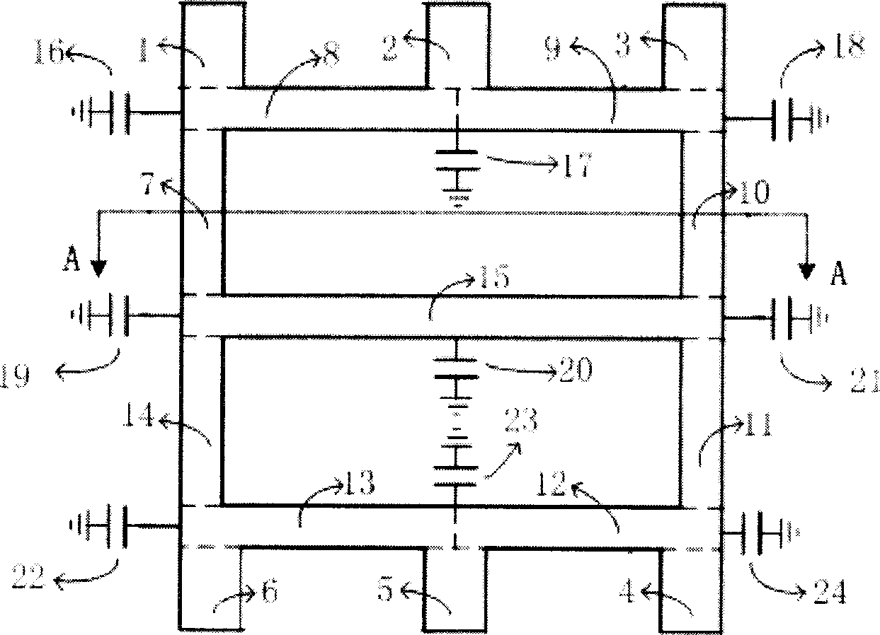
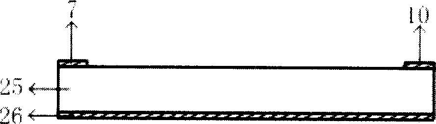
[0037] Such as figure 1 As shown, it is necessary to design a power divider applied to the indoor signal distribution coverage system that inputs from port 1, outputs from ports 2, 4, and 6, and has a power distribution ratio of 1:1:1. The microwave power divider includes a microstrip line, a microwave dielectric substrate 25 and a grounding plate 26. The microstrip line is processed on one side of the microwave dielectric substrate 25 through printed circuit board technology, and the other side is a grounding plate 26. The grounding plate 26 is copper foil Prepared, the microstrip lines 7, 8, 9, 10, 11, 12, 13, 14 are connected to form a square, and each side of the square is formed by connecting 2 sections of equivalent 1 / 4 wavelength lines, and the left and right sides of the square are 2 sections, etc. The effective 1 / 4 wavelength microstrip lines 7...

Embodiment 2

[0041] Embodiment 2 Power splitter applied to antenna array feed network

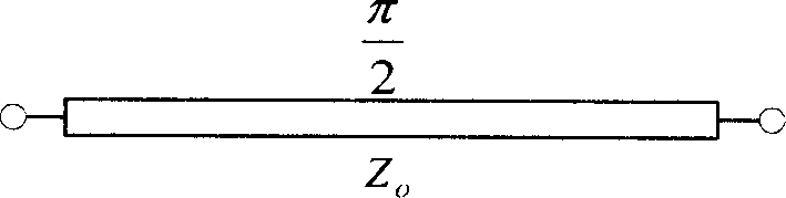
[0042] Such as figure 1 As shown, it is necessary to design a power divider applied to the antenna array feed network with the input from port 1, the output from ports 2, 4, and 6, and the power distribution ratio is 4:2:1, where the impedance of the microstrip line at the output and input ports Both are 50 ohms. According to the analysis described in embodiment 1, determine the characteristic impedance of each section equivalent 1 / 4 wavelength microstrip line and 1 / 2 wavelength microstrip line, Z can be obtained 7 = Z 9 =76.4 Ohm, Z 8 = Z 10 = 66.1 Ohm, Z 11 = Z 13 = 61.2 Ohm, Z 12 = Z 14 =86.6 Ohm, Z 15 = 50 Ohm. According to the above analysis, the electrical length and capacitance are respectively φ = arcsin ( Z o Z ) , C ...


PUM


Abstract

This invention relates to a microwave power splitter having multiple kinds of power splitting ratios, in which, the microstrip lines of said power splitter form a square, every edge of which is connected by two equivalent 1 / 4 wavelength lines, the cross points of two equivalent 1 / 4 wavelength lines at the right and left of the square are connected by an equivalent 1 / 2 line and the property impedance, the electric length and loaded capacitance value are determined by the output power distribution ratio of the power splitter, which gets high isolation without using any isolation resistors and the stationary ratio is good.

Description

technical field [0001] The invention relates to a microwave power splitter, in particular to a microwave power splitter with a microstrip line in a square structure and utilizing capacitive loading technology with various power distribution ratios. Background technique [0002] The full name of microwave power divider is microwave power divider, which is widely used in microwave circuits, especially microwave integrated circuits. At present, for small and medium power two-way microwave power splitters, most of them use microstrip three-port power splitters. For a three-port power divider with no loss and reciprocity, it is impossible for the three ports to match at the same time, so the Wilkinson structure is generally used, and isolation resistors are used to improve the isolation between ports and the matching of each port. For multi-channel microwave power splitters, a common method is to use multiple power splitters divided into two for cascading expansion to obtain pow...

Claims


Application Information

Patent Timeline
Patent Type & Authority Applications(China)
IPC IPC(8): H01P3/08
Inventor 胡斌杰章秀银
Owner SOUTH CHINA UNIV OF TECH
Why Eureka
Try Eureka