Laser rapid-forming method based on contour scanning of coated powder materials

A technology of laser rapid prototyping and powder materials, which is applied in laser welding equipment, instruments, electrical digital data processing, etc., can solve the problems of low strength and inability to process powder materials, and achieve high density and strength, forming speed and efficiency Improvement, the effect of high surface finish

Inactive Publication Date: 2006-09-06
DALIAN UNIV OF TECH
View PDF0 Cites 22 Cited by
  • Summary
  • Abstract
  • Description
  • Claims
  • Application Information

AI Technical Summary

Problems solved by technology

[0012] The purpose of the present invention is to provide a laser rapid prototyping method based on the scanning of the contour line of the coated powder material; the present invention can directly make a three-dimensional computer model into a three-dimensional entity, retains the advantages of the SLS method, and overcomes the low strength of the SLS molded body. The LOM method cannot process powder materials and other deficiencies;

Method used


Image

  • Laser rapid-forming method based on contour scanning of coated powder materials
  • Laser rapid-forming method based on contour scanning of coated powder materials
  • Laser rapid-forming method based on contour scanning of coated powder materials

Examples


Embodiment 1

[0027] Embodiment 1: Manufacture "8" font entity

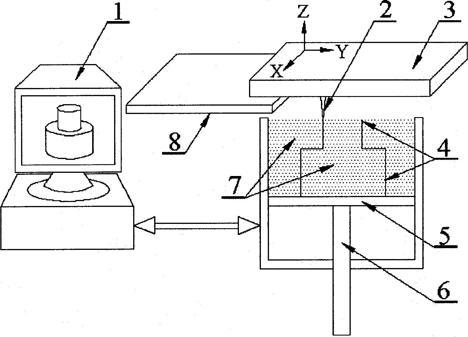
[0028] Firstly, the modeling design of the "8"-shaped three-dimensional CAD model is completed in the computer 1, and then layered in the Z direction, with a layer thickness of 0.6 mm, and the contour line information of each layer is extracted. Turn on the laser and adjust the power of the laser, and start the motion control system. Lay a layer of thick film-coated powder material on the workbench 5, and the laser beam 2, under the control of the computer 1, scans the two-dimensional profile of the layer of powder material in the shape of "8", so that the two-dimensional profile of the current layer The film-coated powder material on the line heats up until it loses its sintering performance, and then the computer controls the piston 6 to descend by 0.6 mm to carry out the next layer of powder spreading and contour scanning until the three-dimensional contour 4 required for molding is scanned. The whole coating powder materi...

Embodiment 2

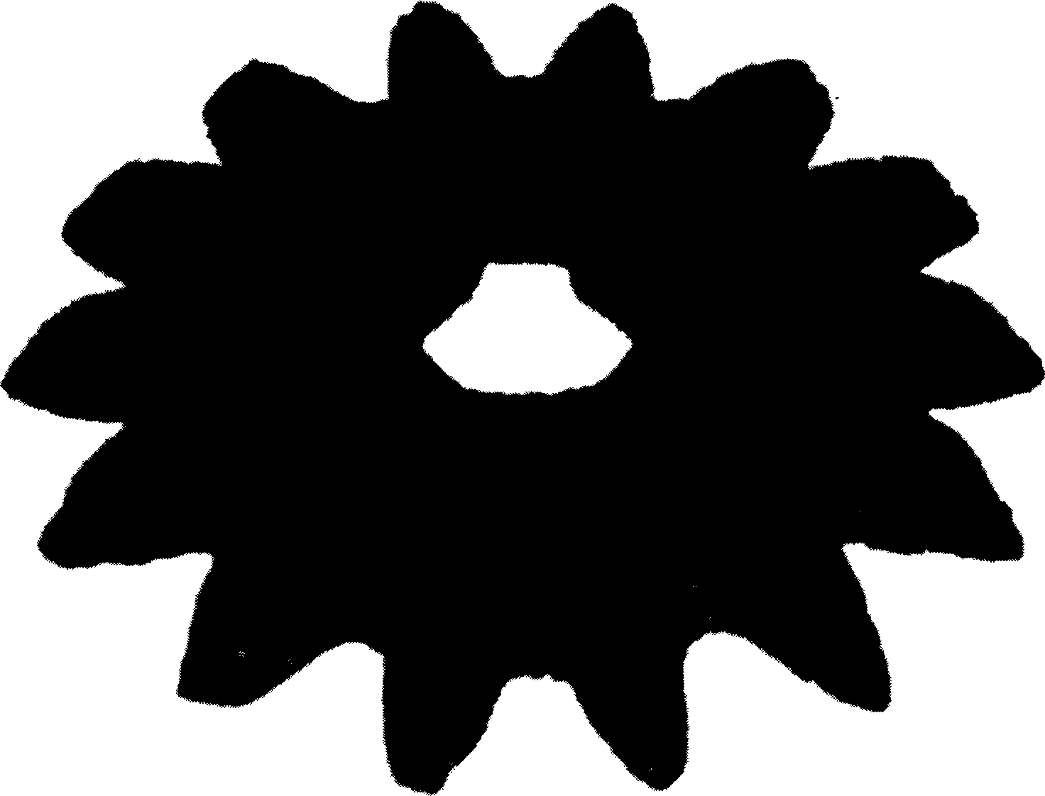
[0029] Example 2: Manufacture of bevel gears

[0030] Firstly, the modeling design of the three-dimensional CAD model of the bevel gear is completed in the computer 1, and then layered in the Z direction, with a layer thickness of 0.6 mm, and the contour line information of each layer is extracted. Turn on the laser and start the computer control system. Lay a layer of thick film-coated powder material on the workbench 5, and the laser beam 2 scans the two-dimensional contour of the bevel gear on the layer of powder material under the control of the computer, so that the powder on the two-dimensional contour line of the current layer The material is heated up until it loses its sintering properties, and then the computer controls the piston 6 to descend by 0.6 mm to carry out the next layer of powder spreading and contour scanning until the three-dimensional contour 4 required for molding is scanned. The coating powder material 7 is preheated on a heating plate for 5 minutes,...


PUM


Abstract

The invention relates to a laser quick molding method based on coating powder material figure scanning, belonging to the laser quick molding technique. The invention first uses the computer, according to the z-direction layered figure information of three-dimensional CAD mold, to control the laser beam to scan the figure of coating powder material; the coating powder material scanned by laser beam is heated and increases temperature to the solid temperature of said powder material; the outer surface coating layer of said powder material loses the solidify property, to form the ineffective division line consistent with the figure; then the piston of workbench decreases one layer to be laid with powder and scan figure until finishing the three-dimensional figure scanning; at last, heating the whole of coating powder while the attained solidified element is separated at the bound of three-dimensional figure which has lost the solidify property, to attain the three-dimensional solid. The invention can quickly make complex three-dimensional solid, with high efficiency, compactness, strength, accuracy and surface fineness.

Description

technical field [0001] The laser rapid prototyping method based on the contour line scanning of coated powder materials belongs to the laser processing rapid prototyping method. [0002] In the technical field, it particularly relates to a method for making a computer three-dimensional model into a part or a sample. Background technique [0003] Laser rapid prototyping technology is a high-tech manufacturing technology that matured and began to be commercialized in the middle and late 1980s. Laser rapid prototyping technology can quickly convert the computer-aided design model (CAD model) of product parts into physical models, part prototypes or parts. Laser rapid prototyping is directly driven by the CAD model, and the corresponding physical entity can be obtained only by changing the CAD model, which greatly shortens the production cycle from conceptual model design to production of products or samples. [0004] At present, there are three main commercialized laser rapid...

Claims


Application Information

Patent Timeline
Patent Type & Authority Applications(China)
IPC IPC(8): B23K26/00B22F3/105B29C67/02G05B15/00G06F17/50
Inventor 姚山曾锋叶昌科陈宝庆
Owner DALIAN UNIV OF TECH
Why Eureka
Try Eureka