Hydrodynamic bearing and method for manufacturing the same, and spindle motor and method for manufacturing the same
A technology of a fluid bearing and a manufacturing method, which is applied to sliding contact bearings, bearings in rotary motion, bearings, etc., can solve the problem that the impact resistance cannot be satisfied, the tightening force of the shaft 34 and the rotor hub 32 is reduced, and the welding fumes are easy to enter the screw. holes, etc., to achieve the effect of suppressing scattering
- Summary
- Abstract
- Description
- Claims
- Application Information
AI Technical Summary
Problems solved by technology
Method used
Image

Examples
Embodiment approach 1
[0139] Below, refer to Figure 1 to Figure 5 , the spindle motor 100 using the bearing device 101 which is the dynamic pressure fluid bearing of this embodiment will be described.
[0140] [Configuration of Spindle Motor 100 ]
[0141] The spindle motor 100 is mainly composed of stationary parts and rotating parts.
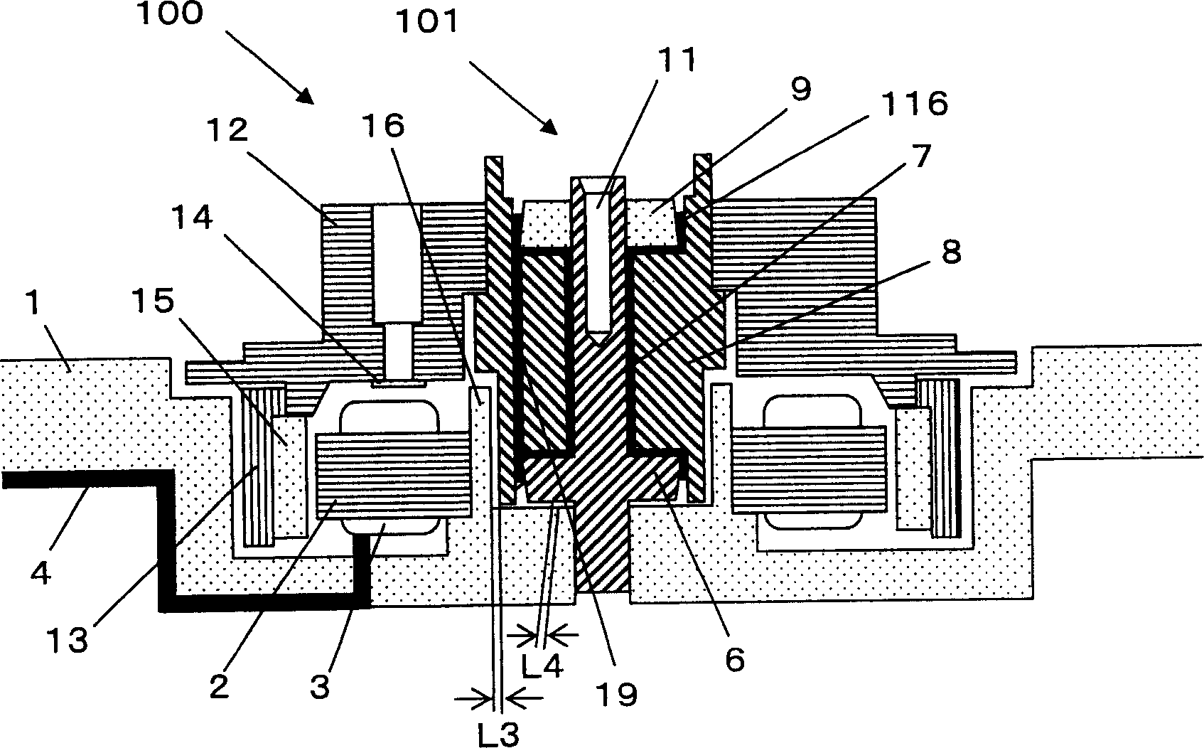
[0142] So-called stationary parts, for example, such as figure 1Shown are a base plate 1 , a stator core 2 , a coil 3 , an insulating tube 4 , a first flange member 6 , a shaft 7 , a second flange member 9 , and a cylindrical wall portion 16 . The bottom plate 1 is made of aluminum alloy or the like. The stator core 2 is made of a silicon steel plate or the like, and a stator core assembly is formed by winding a coil 3 made of a copper-based metal or the like. The stator core assembly is fixed to the base plate 1 by press fitting or the like. One end of the insulating tube 4 is inserted into the coil lead wire, and the other end is drawn out to the outside o...
Embodiment approach 2
[0194] refer to Figure 10 ~ Figure 12 , the spindle motor 200 of this embodiment will be described.
[0195] Figure 10 is a sectional view of the spindle motor 200 .
[0196] exist Figure 10 Among them, the housing 51 has a cylindrical portion 51a at the center, and the boss 52 is attached to the cylindrical portion 51a. The shaft 53 is rotatably inserted into the bearing hole 52 a of the sleeve 52 . A flange 55 is attached to the lower end of the shaft 53 . The opening at the lower end of the bushing 52 is sealed by a thrust plate 54 . Fluids such as oil are filled between the shaft 53 and the sleeve 52, and between the thrust plate 54 and the flange 55, forming a well-known dynamic pressure fluid bearing in this technical field.
[0197] In this embodiment, aluminum casting or iron material is used for the casing 51 . As the bushing 52, a brass material (copper alloy) plated with nickel is used. A stainless steel material (for example, SUS420J2) is used for the sh...
other Embodiment approach
[0209] (A)
[0210] In the above Embodiment 1, with Figure 4 As an example, an example in which the vicinity of the boundary line between the shaft 7 and the second flange member 9 is laser welded in order to fix the second flange member 9 on the shaft 7 will be described. At this time, the shape of the second flange member 9 is not limited to this, either. For example, if Figure 6 As shown in (a), the second flange member may have a concave portion on the inner peripheral side of the upper end surface in the axial direction, and laser welding may be performed near the boundary between the bottom surface of the concave portion 5 and the shaft 7 .
[0211] As an effect of the recessed portion 5, there are effects of preventing warping of the second flange member 9 formed by welding and preventing scattering of foreign matter.
[0212] if press Figure 4 In the welding shown in the configuration, a load is applied in a direction in which the upper end surface of the second...
PUM
 Abstract
Description
Claims
Application Information