
Method for manufacturing copper wire rod and winding device

A technology of a winding device and a manufacturing method, which is applied in the directions of manufacturing tools, conveying filamentous materials, and other manufacturing equipment/tools, etc., can solve problems such as difficulty in forming coils, and achieve the effect of suppressing damage.

Inactive Publication Date: 2006-09-20
MITSUBISHI MATERIALS CORP
View PDF1 Cites 8 Cited by
  • Summary
  • Abstract
  • Description
  • Claims
  • Application Information

AI Technical Summary

Problems solved by technology

[0011] However, according to the above-mentioned manufacturing method, for example, it is difficult to form a coil in a large-diameter wire-shaped copper base material with a wire diameter of 25 mm or more, so the wire-shaped copper base material is formed as a vertically long rod-shaped copper base material with a length of several meters. Production, and therefore a long-distance area is required as a production line and storage space
In addition, according to the improvement of operability as described in Patent Document 1, the improvement of productivity can only be expected to have a limited effect, so a dramatic improvement in productivity and quality is expected.

Method used


Image

  • Method for manufacturing copper wire rod and winding device
  • Method for manufacturing copper wire rod and winding device
  • Method for manufacturing copper wire rod and winding device

Examples


Embodiment Construction

[0036] Hereinafter, embodiments of the present invention will be described with reference to the drawings.

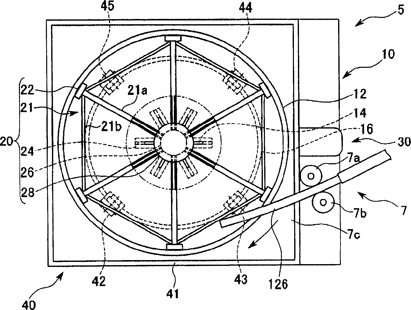
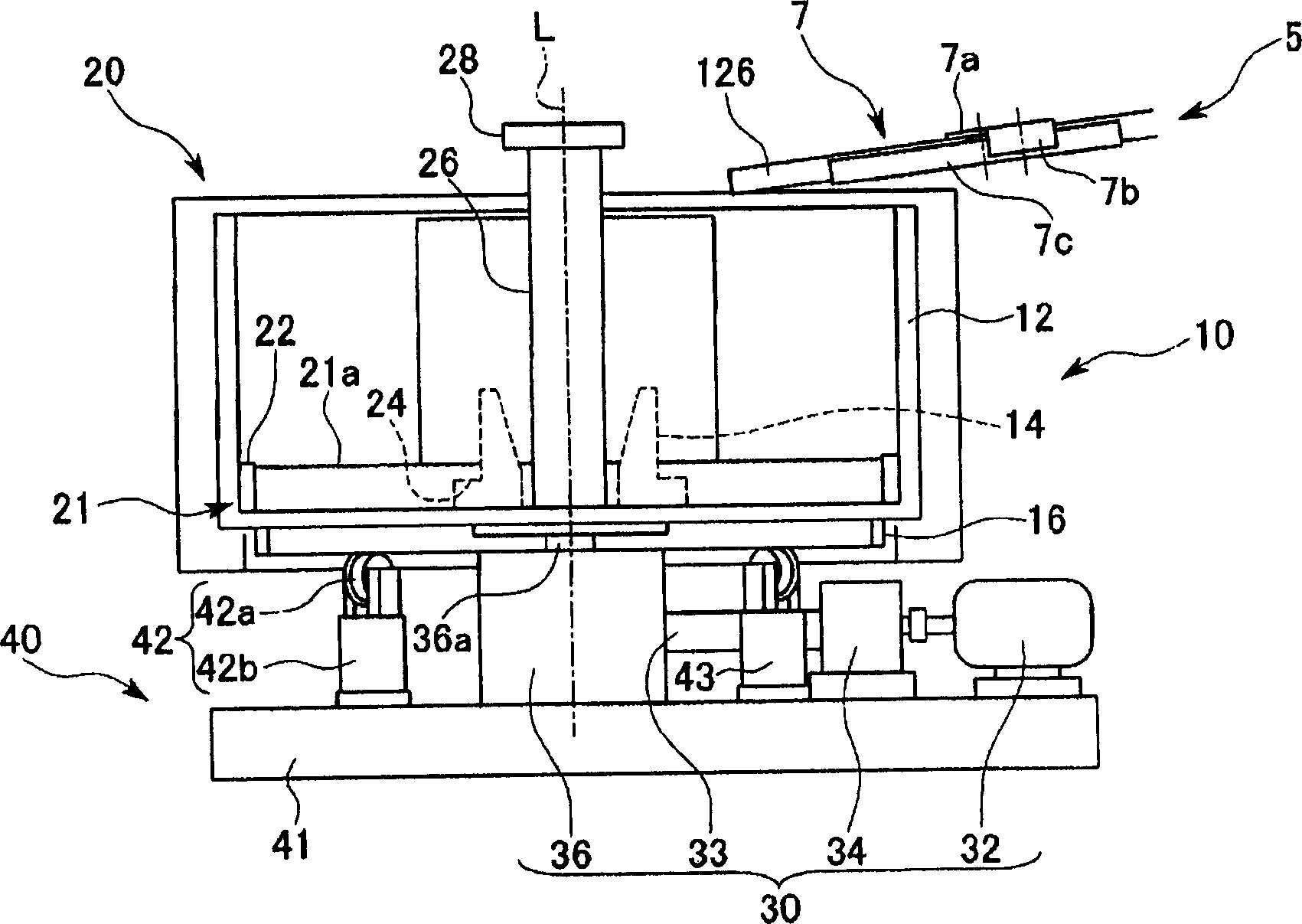
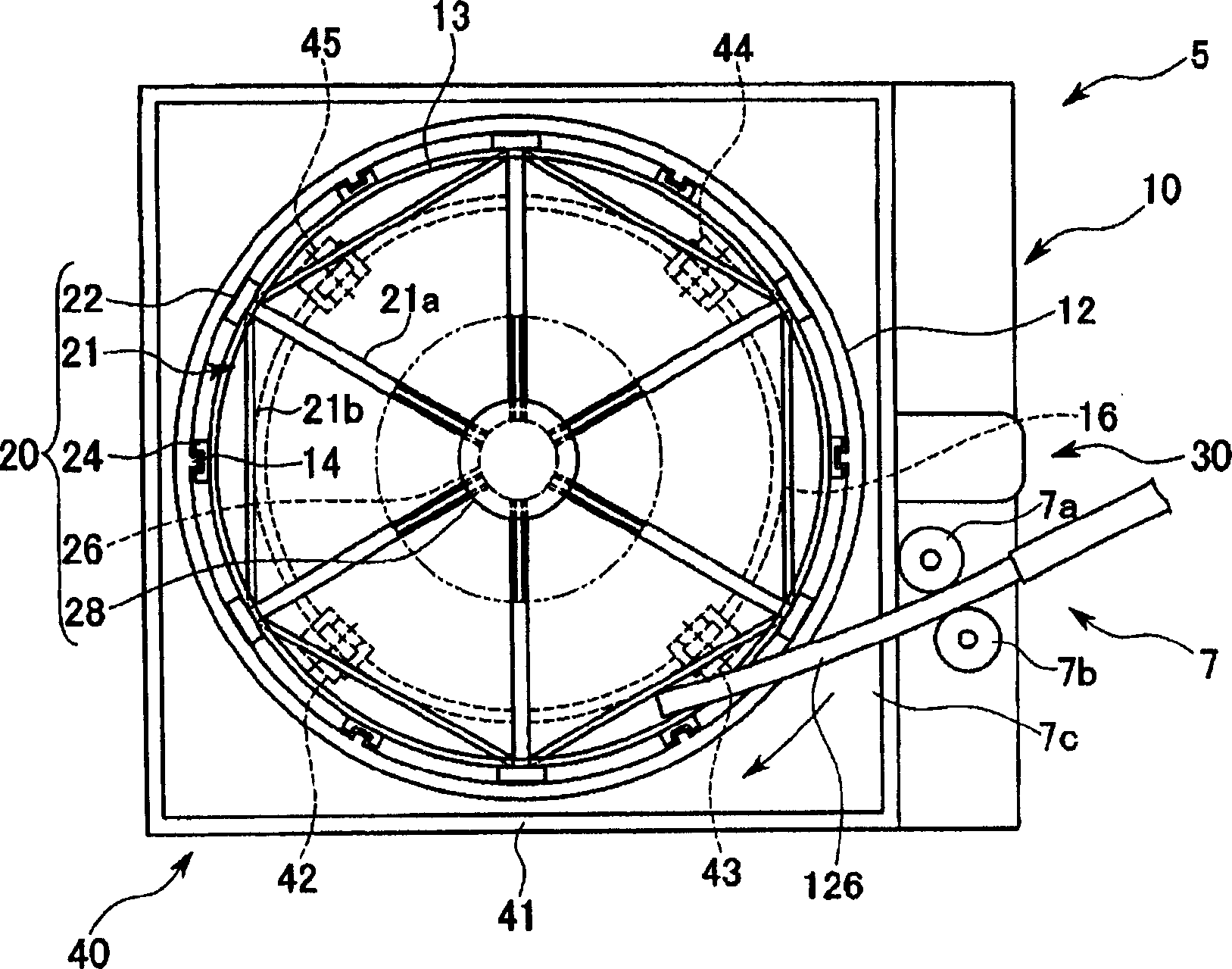
[0037] The manufacturing process of the coil-shaped linear copper base material (hereinafter referred to as the coil-shaped copper base material) of the present embodiment is as described above. image 3 As shown, it is composed of a melting furnace A, a holding furnace B, a casting barrel C, a belt type continuous casting machine D, a calender E, and a winding device 5, and the process M shown by a two-dot dash line replaces the existing coil Since the thread machine F is different from the winding device of the present invention, the other parts are the same, so the same reference numerals are assigned and descriptions thereof are omitted.

[0038] The following is based on figure 1 , figure 2 , and the configuration of the thermal winding device according to the first embodiment of the present invention will be described.

[0039] Winding device 5, such as fig...


PUM


Abstract

The invention relates to a method for producing line copper mother metal of coil, and relative winding machine, which can improve the quality and the efficiency, and coil present line copper mother metal whose diameter is more than 25mm, to improve the operational property. The winding machine continuously winds the line copper mother metal the guided out from the continuous casting machine and compressed extend in the compress extend process. It is characterized in that: it has a cooling reduction groove (10) which can keep the reduction solution that dipping said line copper mother metal; and a winding axle (2) inside said cooling reduction groove (10).

Description

technical field [0001] The present invention relates to a method for manufacturing a coil-shaped wire-shaped copper base material and a winding device for winding it into a coil shape. coiled. Background technique [0002] For example, when the wiring pattern of a printed circuit board is formed by copper plating, especially copper sulfate plating, an anode (positive electrode) formed in a rod shape, a wire shape, a ball shape, etc. is used, because the material is supplied to the plating line It is easy to provide in the form of rolling, so spherical positive electrodes for copper plating are widely used. [0003] Figure 5 The production process of the conventional linear copper base material, such as the copper base material for copper electroplating, is shown. Process 1, its composition is roughly divided into: melting furnace A, which produces molten copper (hereinafter referred to as molten metal); holding furnace B, which is used to maintain the temperature of molte...

Claims


Application Information

Patent Timeline
Patent Type & Authority Applications(China)
IPC IPC(8): B23P23/04B65H54/02
CPCG06Q50/06
Inventor 田村康人椿茂男
Owner MITSUBISHI MATERIALS CORP
Learn More