Exhaust gas catalytic converter

一种催化净化、尾气的技术,应用在排气装置、催化剂活化/制备、非均相催化剂化学元素等方向,能够解决发动机室变窄等问题

Inactive Publication Date: 2006-10-18
MAZDA MOTOR CORP
View PDF1 Cites 11 Cited by
  • Summary
  • Abstract
  • Description
  • Claims
  • Application Information

AI Technical Summary

Problems solved by technology

However, in recent years, there has been a tendency that, due to the improvement of vehicle habitability, the cabin has to be wider, and the engine room has become narrower.

Method used


Image

  • Exhaust gas catalytic converter
  • Exhaust gas catalytic converter
  • Exhaust gas catalytic converter

Examples


Embodiment Construction

[0037] Hereinafter, embodiments of the present invention will be described in detail with reference to the drawings.

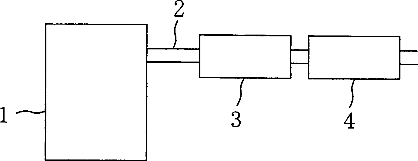
[0038] figure 1 Among them, 1 is the engine of the automobile, 2 is the exhaust gas discharge passage, 3 is the upstream side catalyst (three-way catalyst) arranged on the upstream side of the exhaust gas flow in the exhaust gas discharge passage 2, and 4 is the downstream catalyst (three-way catalyst) arranged on the downstream side. Side catalyst (three-way catalyst).

[0039]

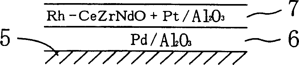
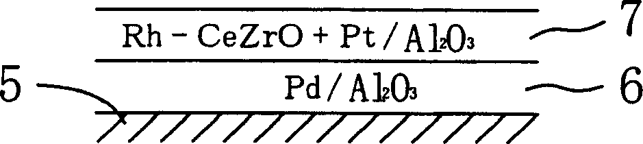
[0040] in order to figure 1 The respective catalyst devices constituting the Examples and Comparative Examples under the catalyst arrangement shown were prepared to produce Figure 2 to Figure 4 Three catalysts A, B, C are shown. Each of the catalysts is formed by laminating an inner catalyst layer 6 on the cell wall side and an outer catalyst layer 7 directly exposed to exhaust gas on a cell wall 5 of a honeycomb carrier (hereinafter referred to as carrier).

[0041] (for Cata...


PUM


Abstract

The invention discloses a tail gas catalytic purification device. The device comprises: two catalysts 3, 4 respectively arranged on the upstream side and the downstream side of the exhaust gas flow in the exhaust gas discharge passage of the engine. The upstream side catalyst 3 and the downstream side catalyst 4 each contain an oxygen storage material, and the oxygen storage material of the upstream side catalyst 3 is formed by arranging rhodium at or between crystal points of a composite oxide containing cerium and zirconium, The oxygen storage amount of the oxygen storage material of the upstream side catalyst 3 is larger than the oxygen storage capacity of the oxygen storage material of the downstream side catalyst 4 at the same temperature. Therefore, the present invention can improve the purification performance which is the basic performance of the exhaust gas purification catalyst device, ensure heat resistance, and achieve miniaturization of the device or improvement of layout.

Description

technical field [0001] The invention relates to an exhaust gas catalytic purification device for purifying the exhaust gas of an automobile engine. Background technique [0002] In the automotive exhaust purification technology in recent years, the following situations are increasing. That is, a direct catalyst (manifold catalyst) directly connected to the exhaust manifold for early activation after engine startup and a catalyst placed on the underbody of the vehicle to purify the exhaust gas that cannot be completely purified by the direct catalyst are used at the same time. Or more than one floor catalyst. In order to achieve early activation, the floor catalyst is arranged as close to the engine as possible, but like the direct catalyst, the catalyst precious metal will be sintered by the heat of the exhaust gas. this is a problem. [0003] As a solution to this problem, the applicant of the present application proposed a catalyst for purifying exhaust gas described in...

Claims


Application Information

Patent Timeline
Patent Type & Authority Applications(China)
IPC IPC(8): B01D53/94F01N3/28
CPCB01D53/945B01D53/9454B01D2255/407B01J21/066B01J23/002B01J23/63B01J37/0244B01J37/0248B01J37/03B01J2523/00F01N3/0814F01N2370/02F01N2510/06F01N2570/16F01N13/0093F01N13/009Y02T10/12B01J35/19B01J2523/3712B01J2523/3725B01J2523/48B01J2523/822
Inventor 三好诚治山田启司高见明秀
Owner MAZDA MOTOR CORP
Why Eureka
Try Eureka