Optical printing head and its usage

A print head and optical technology, applied in the field of optical print heads, can solve the problems of shortening the service life of light emitting diodes 10a, reducing optical coupling efficiency, and high temperature

Inactive Publication Date: 2006-10-18
LITE ON TECH CORP
View PDF0 Cites 4 Cited by
  • Summary
  • Abstract
  • Description
  • Claims
  • Application Information

AI Technical Summary

Problems solved by technology

[0002] Generally, the optical print head that uses a diode light-emitting board as a light source, because its optical coupling efficiency is not high, so it is necessary to increase the driving current to make the diode light-emitting board generate higher energy irradiation light, and the diode light-emitting board needs about 5 ~20A (depending on the design of the drive circuit) working current, so after a period of continuous work, there will be a problem of overheating
[0003] Please refer to Figure 1A , which is a schematic diagram of light rays traveling in the prior art optical printing head, and the upper figure in the figure is a front schematic view of the single-row self-focusing microlens group 20, here, along the A-A' of the single-row self-focusing microlens group 20 The section of the line segment is illustrated by the lower figure in the figure. When the light emitting diode 10a generates the irradiating light 17, the irradiating light 17 scatters part of the irradiating light 17 to areas other than the self-focusing microlens 20a as the distance increases. Therefore, Only part of the irradiating light 17 enters the self-focusing microlens 20a, such a process will cause the light coupling efficiency to decrease, and the light coupling efficiency of some designs is even only 0.4217%. After the focusing microlens 20a, the receiving end only receives 0.004217mw of light s

Method used


Image

  • Optical printing head and its usage
  • Optical printing head and its usage
  • Optical printing head and its usage

Examples


Embodiment Construction

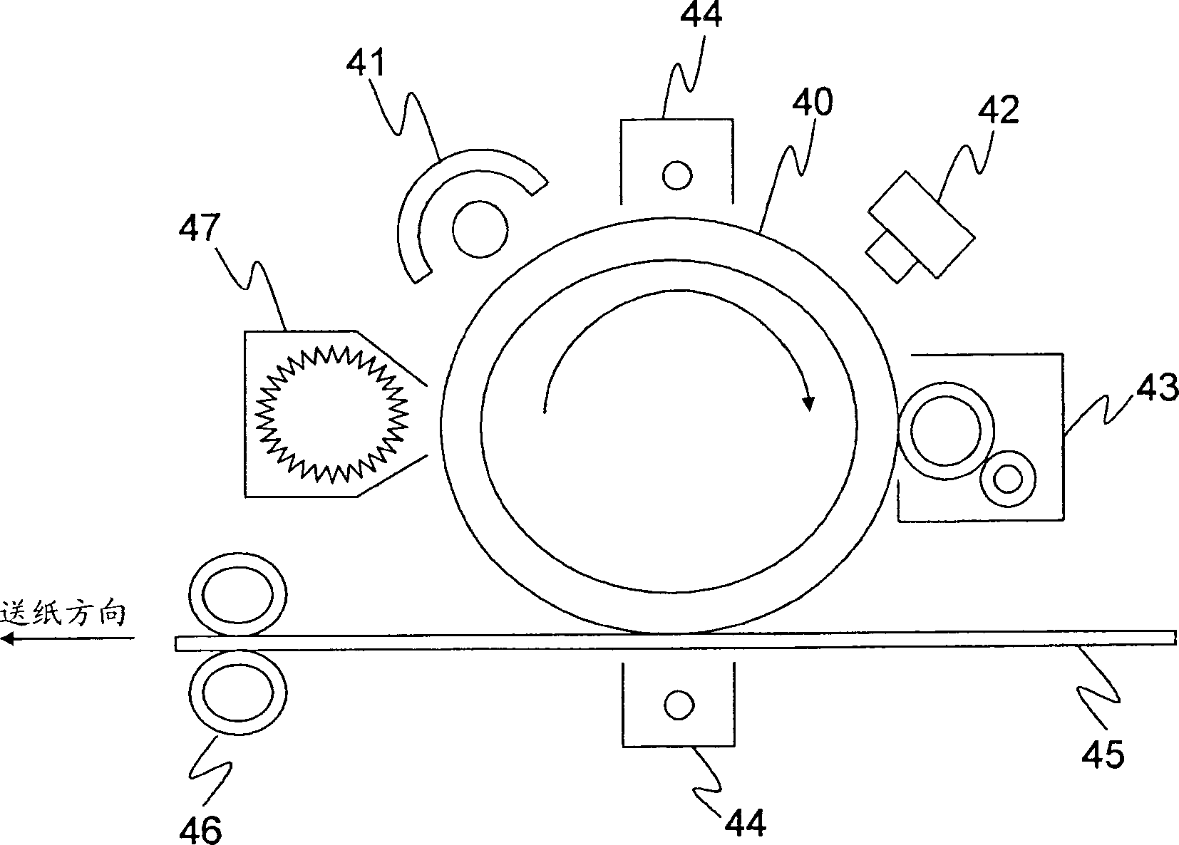
[0034] First, please refer to figure 2 , which is a schematic diagram of the system structure of the optical printer according to the present invention, including: a photosensitive drum unit 40, a power distribution unit 41, an optical print head unit 42, a developing unit 43, a transfer unit 44, paper 45, a heating unit 46 and Clear unit 47.

[0035] The photosensitive drum unit 40 is a core module in an optical printer, and has the characteristic of changing conductivity upon exposure to light. For example, after the exposure process, the photosensitive drum unit 40 has conductivity, and the unexposed part is an insulator.

[0036] The electricity distributing unit 41 is used for distributing electricity or eliminating static electricity on the surface of the photosensitive drum unit 40 , so as to generate a layer of static charge on the surface of the photosensitive drum unit 40 or eliminate the static electricity on the surface of the photosensitive drum unit 40 .
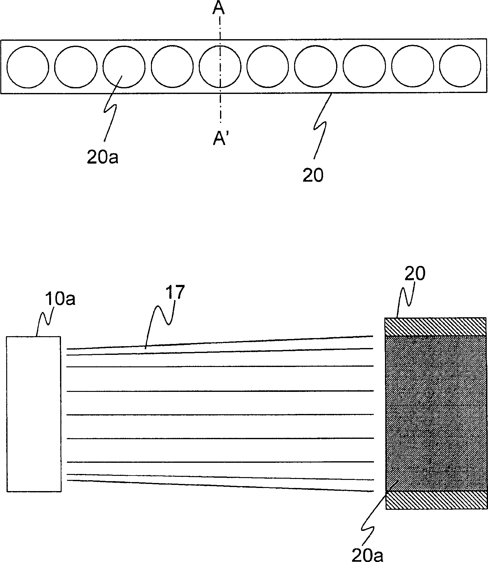
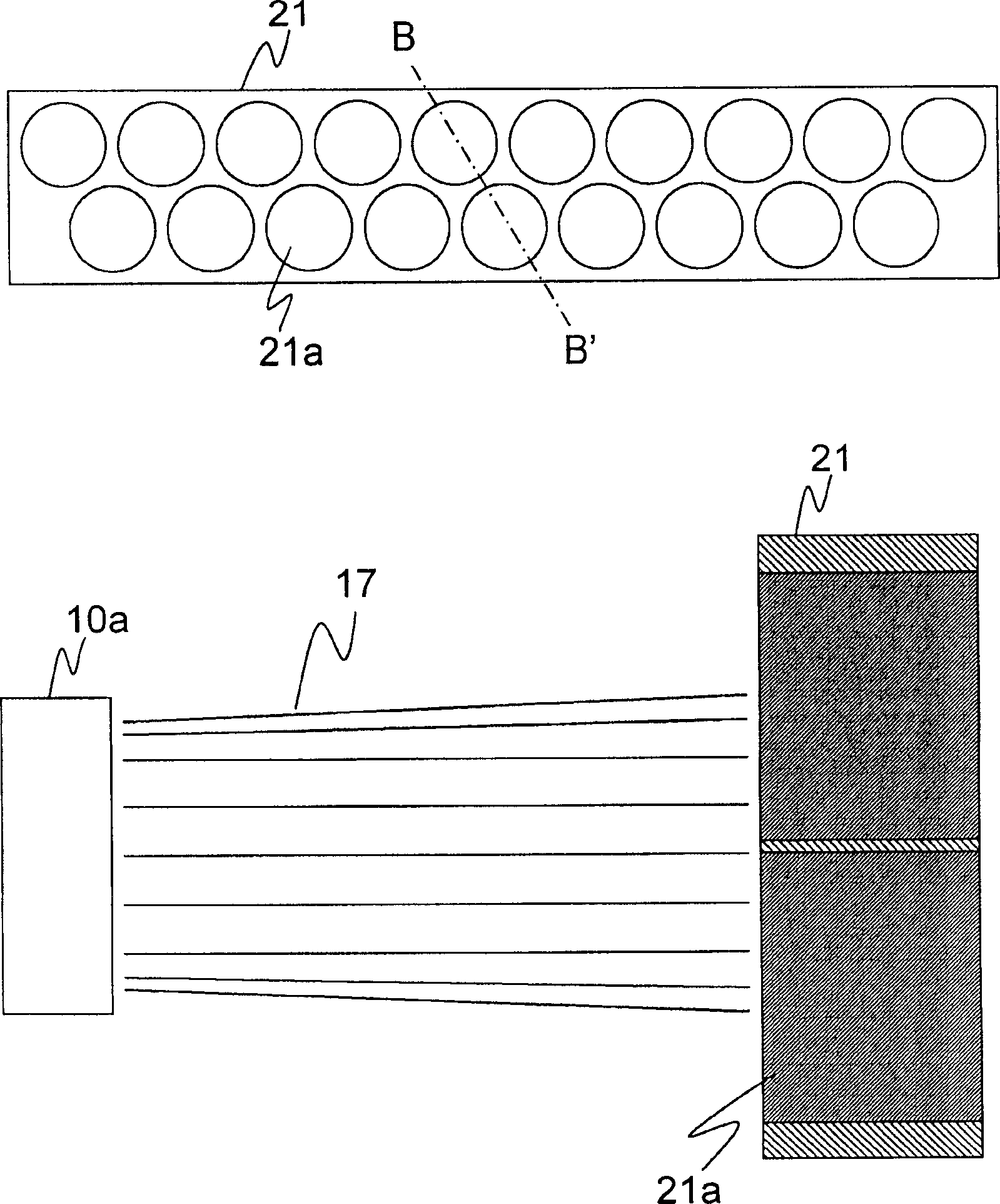
[003...


PUM


Abstract

The present invention is one optical printing head and its usage. The optical printing head has matrix form condensing micro lens combination set between its LED plate and the matrix form self-focusing micro lens combination to converge the light from the LED plate to the matrix form self-focusing micro lens combination to raise the light strength to the matrix form self-focusing micro lens combination and raise the photocoupling efficiency.

Description

technical field [0001] The present invention relates to an optical printing head and its usage method, especially an optical printing head with high optical coupling efficiency and its usage method. Background technique [0002] Generally, the optical print head that uses a diode light-emitting board as a light source, because its optical coupling efficiency is not high, so it is necessary to increase the driving current to make the diode light-emitting board generate higher energy irradiation light, and the diode light-emitting board needs about 5 The operating current is about 20A (depending on the design of the drive circuit), so after a period of continuous operation, the problem of overheating will occur. [0003] Please refer to Figure 1A , which is a schematic diagram of light rays traveling in the prior art optical printing head, and the upper figure in the figure is a front schematic view of the single-row self-focusing microlens group 20, here, along the A-A' of t...

Claims


Application Information

Patent Timeline
IPC IPC(8): B41J2/45
Inventor 林勇杉
Owner LITE ON TECH CORP
Why Eureka
Try Eureka