

Catalyst component for olefinic polymerization and its catalyst
A technology of olefin polymerization and catalyst, which is applied in the field of ketone compounding, and can solve the problems of narrow polymer molecular weight distribution and reduced hydrogen sensitivity
- Summary
- Abstract
- Description
- Claims
- Application Information
AI Technical Summary
Problems solved by technology
Method used
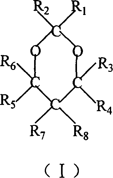
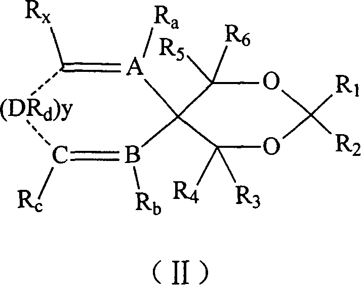
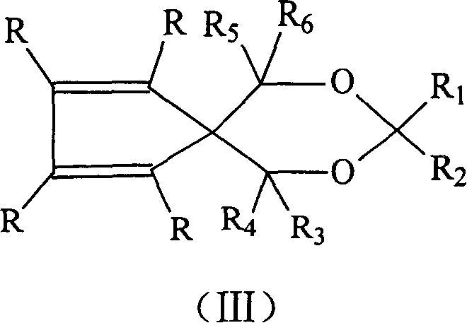
Image

Examples
Embodiment 1
[0185] Example 1 Synthesis of 1,3-dibenzo-7,9-dioxaspiro[4.5]decane
[0186] Add 6.78g (0.03mol) of 9,9-dimethylolfluorene, 0.57g (0.003mol) of p-toluenesulfonic acid, and 1.00g (0.033mol) of paraformaldehyde into 120ml of benzene, and heat to reflux for 4h. The reaction mixture was cooled to room temperature, transferred to a separatory funnel, washed successively with aqueous sodium bicarbonate solution and saline solution, dried over anhydrous magnesium sulfate, filtered, and desolventized to obtain a yellow viscous oil, which was recrystallized with ethanol to obtain white crystals 3.21g, yield 45.0%, m.p.92-93°C.
[0187] 1 H NMR (400MHz, CDCl 3 )δ (ppm): 3.98 (s, 4H, 2OCH 2 ), 5.22(s, 2H, OCH 2 O), 7.25-7.80 (m, 8H, ArH).
Embodiment 2
[0188] Example 2 Synthesis of 1,3-dibenzo-7,9-dioxa-8,8-dimethylspiro[4.5]decane
[0189] Add 6.78g (0.03mol) of 9,9-dimethylolfluorene, 0.57g (0.003mol) of p-toluenesulfonic acid, and 3.48g (0.06mol) of acetone into 75ml of benzene, and heat to reflux for 4h. The reaction mixture was cooled to room temperature, transferred to a separatory funnel, washed successively with aqueous sodium bicarbonate solution and saline solution, dried over anhydrous sodium sulfate, filtered, and desolventized to obtain a yellow viscous oil, which was recrystallized with ethanol to obtain white crystals 4.04g, yield 54.7%, m.p.96-98°C.
[0190] 1 H NMR (400MHz, CDCl 3 )δ (ppm): 1.72 (s, 6H, 2CH 3 ), 4.02(s, 4H, 2OCH 2 ), 7.24-7.80 (m, 8H, ArH).
Embodiment 3
[0191] Example 3 Synthesis of 1,3-dibenzo-7,14-dioxadispiro[4.2.5.2]pentadecane
[0192] Add 6.78g (0.03mol) of 9,9-dimethylolfluorene, 0.57g (0.003mol) of p-toluenesulfonic acid, and 3.15g (0.032mol) of cyclohexanone into 75ml of benzene, and heat to reflux for 4h. The reaction mixture was cooled to room temperature, transferred to a separatory funnel, washed successively with aqueous sodium bicarbonate solution and saline solution, dried over anhydrous sodium sulfate, filtered, and desolventized to obtain a viscous oil, which was recrystallized with ethanol to obtain white crystal 4.42 g, yield 48.1%, m.p.168-169°C.
[0193] 1 H NMR (400MHz, CDCl 3 )δ (ppm): 1.48-2.10 (m, 10H, 5CH 2 ), 4.00(s, 4H, 2OCH 2 ), 7.32-7.80 (m, 8H, ArH).
PUM
 Abstract
Description
Claims
Application Information