Coal gas cleaning process

A gas washing and process technology, which is applied in the petroleum industry, combustible gas purification, combustible gas purification/reconstruction, etc., can solve the problems of high dust content in washing water, excessive gas waste heat, and easy blockage of equipment, so as to prevent sewage from being forced to Emission problems, saving settlement volume and reducing cost

Active Publication Date: 2006-10-25
刘金成
View PDF0 Cites 9 Cited by
  • Summary
  • Abstract
  • Description
  • Claims
  • Application Information

AI Technical Summary

Problems solved by technology

Through long-term production practice, it is found that the above gas washing and cooling process has the following problems: (1). Because the gas contains more waste heat, and the temperature rise of the washing water in the washing tower is limited by the adiabatic saturation temperature of the gas, it can only reach around 70°C
This results in a large amount of hot water circulation, so that the sedimentation tank 2 requires a large settling volume, resulting in an excessively large footprint and high investment
(2). Since the moisture contained in the gas is condensed and merged into the hot water for washing when it contacts with the washing water for heat exchange, it cannot be completely brought into the air in the cooling tower 5, resulting in a continuous increase in the amount of circulating washing water, and a large amount of sewage is Forced discharge, thereby polluting the environment
(3). Due to the high dust content of the washing water, it is easy to cause the blockage of the filling of the cooling tower 5, which increases the maintenance workload and increases the cost of the enterprise
[0004] The invention provides a separate operation process for washing and dedusting dust-containing, water-vapour-containing gas or semi-water gas and cooling and cooling to solve the problems of the existing process sewage discharge and settlement tanks occupying a large area and easy blockage of equipment

Method used


Image

  • Coal gas cleaning process
  • Coal gas cleaning process
  • Coal gas cleaning process

Examples


Embodiment 1

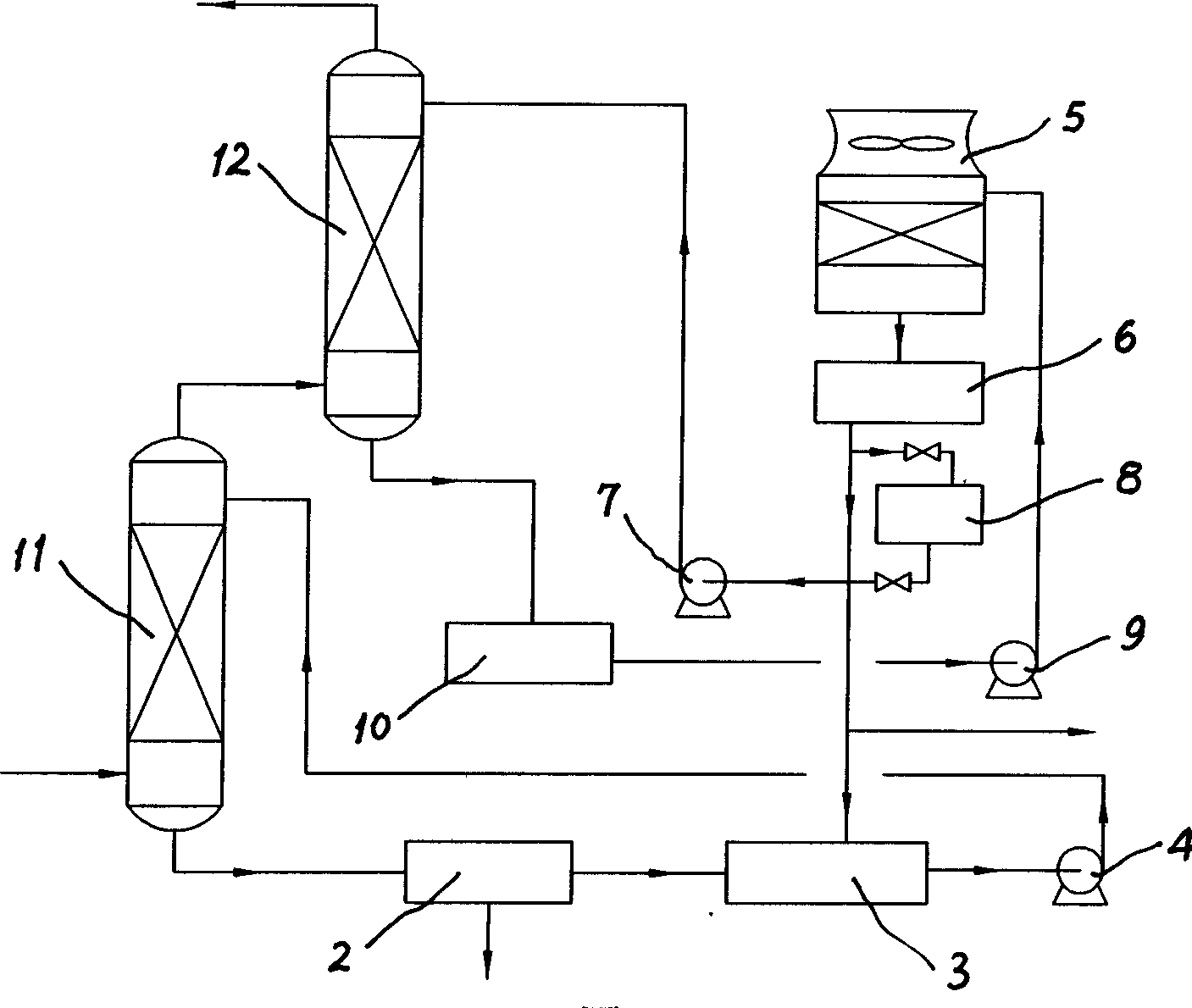
[0022] Embodiment 1: as figure 2 As shown, the gas containing dust and water vapor is passed into the bottom of the washing tower 11, and the gas containing water vapor is countercurrently contacted with the hot water for washing at the top of the tower, and the dust in the gas is washed into the hot water, and the waste water after washing is collected into the sedimentation through the bottom of the tower. Pool 2, the water after the sedimentation of ash flows into the water storage tank 3, and then pressurized by the hot water pump 4 and pumped into the top of the washing tower 11 for recycling. The dust in the gas is washed into the hot water, and at the same time absorbs part of the sensible heat of the gas, so that part of the water evaporates into the gas, so that the temperature of the gas decreases and the moisture content increases. The washed gas enters the cooling tower 12, making it contact with the cooling water pumped from the top of the tower. The cooling wate...

Embodiment 2

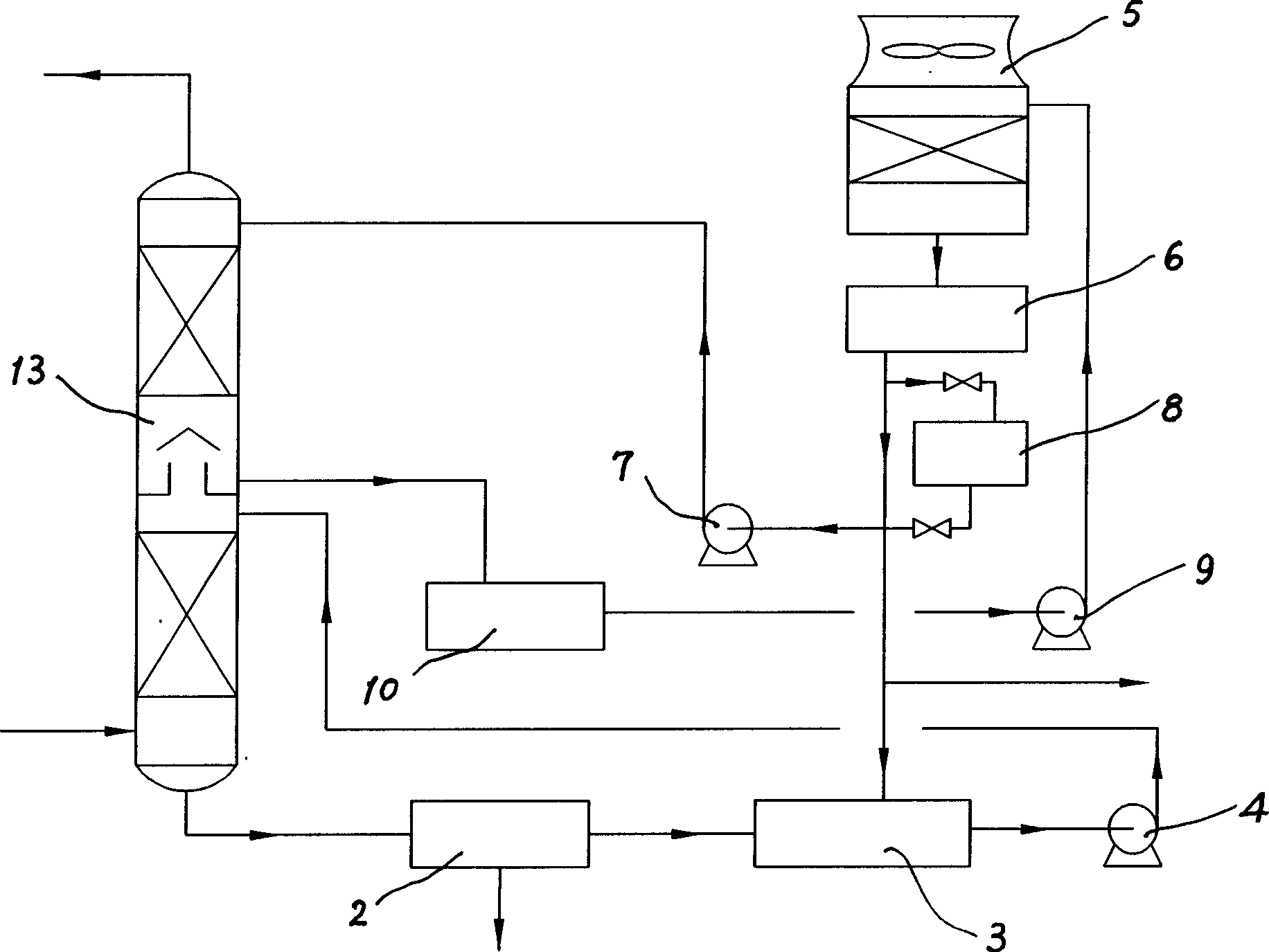
[0023] Embodiment 2: as image 3 As shown, the difference between this embodiment and Embodiment 1 is that the washing tower 11 and the cooling tower 12 can be combined into a composite tower 13, the upper part of the composite tower 13 is a cooling process, and the lower part is a washing process.


PUM


Abstract

The invention relates to a coal gas washing cooling technology that includes the following steps: the dust and vapor containing coal gas passing through washing tower to reversely contact with washing hot water, the washing waste water flowing into tank after deposition, and pumping into washing tower to take recycling using; the washed gas could come into cooling tower to contact with cold water and flow out from the top of the tower, the waste water flowing into tank and pumping into cooling water tower to separate into three channels, one pumping back to the cooling tower, another coming into hot water pool and the other would be discharged from the system. The invention could save invest over 80%, and improve the utilization factor of primal water. It has great social and economic benefits.

Description

technical field [0001] The invention relates to a dedusting and cooling process, in particular to a washing and cooling process for dust-containing, moisture-containing gas or semi-water gas. technical background [0002] In the process of producing water gas or semi-water gas by reacting anthracite and water vapor, the temperature of the gas or semi-water gas produced by the gasifier is generally 110-160°C after sensible heat recovery, and contains more than 0.3Nm 3 / (m 3 Coal gas) around the water vapor, while entraining quite a lot of coal powder and other particles, it needs to be cooled and washed to meet the process requirements. Currently used cooling and washing processes such as figure 1 As shown, the process is that the gas or semi-water gas enters the washing tower 1 and contacts with the washing water added from the top of the tower. The dust in the gas is washed by the washing water and then enters the washing water, and the sensible heat is absorbed by the wa...

Claims


Application Information

Patent Timeline
Patent Type & Authority Applications(China)
IPC IPC(8): C10K1/10
Inventor 刘金成
Owner 刘金成
Why Eureka
Try Eureka