High-precision low-friction magnetic suspension sliding composite guid rail

A low-friction, high-precision technology applied to guide rails. It can solve the problems of unstable performance, high production cost, easy generation of vibration and noise, etc., and achieve the effect of strong load adaptability, anti-vibration ability, strong anti-vibration interference ability, and stable guiding performance.

Inactive Publication Date: 2006-10-25
HEFEI UNIV OF TECH
View PDF0 Cites 14 Cited by
  • Summary
  • Abstract
  • Description
  • Claims
  • Application Information

AI Technical Summary

Problems solved by technology

The traditional sliding guideway has simple structure, good rigidity and strong bearing capacity, but due to the large friction coefficient, it has high requirements for lubrication, high energy consumption, and limited movement speed; the traditional rolling guideway has small friction coefficient, low heat generation and long service life. Long, but poor rigidity, low bearing capacity, difficult to achieve high guiding accuracy and motion stability, and easy to generate vibration and noise at high speeds; air bearing guide rails have developed rapidly in recent years, and their friction, noise, and vibration are very small. High precision, long life, high-speed motion, no need for lubrication, but low load capacity, complex structure, high production cost, cannot be used in a vacuum environment, and the interference of the exhaust air flow to the measurement system needs to be considered; maglev guide rails have been developed in recent years Another new type of guide rail has a large load-carrying capacity, low friction, noise, and vibration. It has no limit to the running speed and does not need lubrication. When using electromagnets, it has no requirements for the environment, and the motion and system characteristics are adjustable and easy to control. However, the system structure is complex, High production cost, unstable performance, difficult control of guiding precision, and difficult to overcome the influence of electromagnet heating
Therefore, when designing modern machine tools and high-precision instruments, it is difficult to choose any kind of guide rail to meet the requirements of load bearing, high speed or low speed, high stability, high guiding accuracy, and low cost at the same time. the bottleneck

Method used


Image

  • High-precision low-friction magnetic suspension sliding composite guid rail
  • High-precision low-friction magnetic suspension sliding composite guid rail
  • High-precision low-friction magnetic suspension sliding composite guid rail

Examples


Embodiment

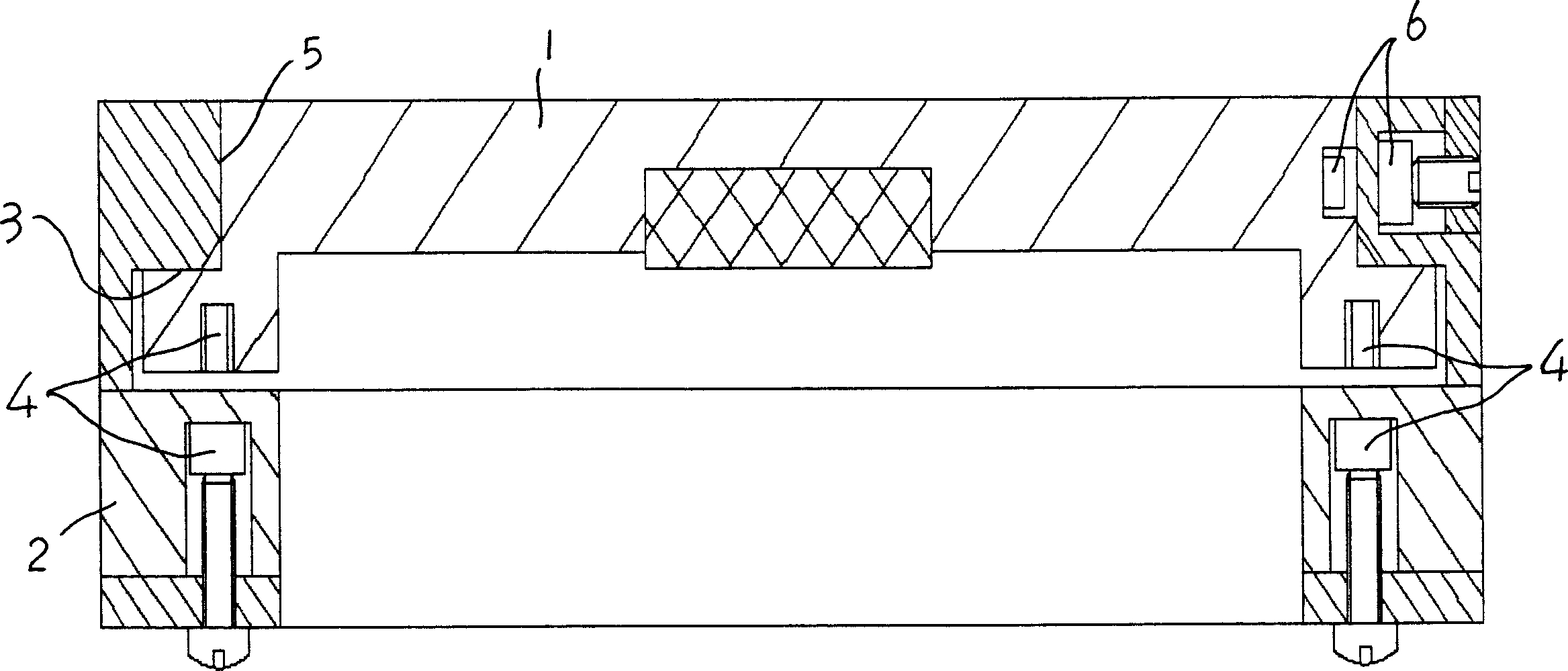
[0018] see figure 1 , the present embodiment is between the bottom end face of moving part 1 and the supporting surface of guide rail 2, a pair of bottom permanent magnet pair 4 is oppositely installed with the same sex, keeps the bottom end face of moving part 1 with the repulsive force that bottom permanent magnet pair 4 forms The supporting surfaces of the guide rail 2 are in a non-contact state, and a positive pressure is formed between the moving part 1 and the top guide surface 3 of the guide rail 2;

[0019] With one side end surface of the moving part 1 and the guide rail 2 as the side guide surface 5, on the other side end surface opposite to the side guide surface 5, the side permanent magnet pair 6 is installed oppositely with the same sex, and the side permanent magnet The repulsive force formed by the magnet pair 6 keeps the moving part 1 and the guide rail 2 in a non-contact state on the side end surface, and forms a positive pressure on the side guide surface 5 ...


PUM


Abstract

This invention relates to a high accuracy low friction magnetic suspension-sliding compound guideway characterizing in mounting a pair of base like magnets oppositely between the end face of the bottom of a mobile piece and the supporting face of the guideway to keep them at an un-contact state by the repulsive force formed by it and form a positive pressure between the top guide faces of the mobile piece and the guideway, taking a side end face of the mobile piece and the guideway as the side guide face to mount a pair of like side magnets oppositely on the other end face opposite to the guide face of the side to keep the mobile piece and the guideway at an un-contact state at the side end face with the repulsive force formed by the pair of magnets to form a positive pressure on the guide face of the side part.

Description

Technical field: [0001] This invention relates to motion guides, more particularly guide rails. Background technique: [0002] The performance of processing machinery and length measuring instruments is inseparable from the characteristics of guide rails. Modern machine tools and high-precision instruments require guide rails to meet fast movement and high-precision positioning. The traditional sliding guideway has simple structure, good rigidity and strong bearing capacity, but due to the large friction coefficient, it has high requirements for lubrication, high energy consumption, and limited movement speed; the traditional rolling guideway has small friction coefficient, low heat generation and long service life. Long, but poor rigidity, low bearing capacity, difficult to achieve high guiding accuracy and motion stability, and easy to generate vibration and noise at high speeds; air bearing guide rails have developed rapidly in recent years, and their friction, noise, and...

Claims


Application Information

Patent Timeline
Patent Type & Authority Applications(China)
IPC IPC(8): H02N15/00B23Q1/26G12B3/00G12B3/06
Inventor 余晓芬奚琳黄斌
Owner HEFEI UNIV OF TECH
Why Eureka
Try Eureka