
Tunable plasma resonant cavity

A plasma and resonant cavity technology, applied in the directions of plasma, gaseous chemical plating, coating, etc., can solve the problem of difficult to cope with the change of the equivalent load of the plasma resonant cavity, the inability to realize the real-time control of the plasma resonant cavity, and the cavity structure. The allowable variation range of size is narrow and other problems, so as to achieve the effect of small loss, simple structure and easy processing.

Inactive Publication Date: 2006-11-08
YANGTZE OPTICAL FIBRE & CABLE CO LTD
View PDF0 Cites 18 Cited by
  • Summary
  • Abstract
  • Description
  • Claims
  • Application Information

AI Technical Summary

Problems solved by technology

Therefore, the allowable range of variation in the size of the cavity structure is relatively narrow, and the requirements for actual processing are very high, otherwise the electromagnetic wave cannot vibrate in the cavity
In addition, in the prior art, a coaxial waveguide is usually provided in the waveguide device, and the matching performance of the waveguide device is adjusted by adjusting the insertion depth of the coaxial inner conductor (antenna) in the coaxial waveguide into the rectangular waveguide. However, the above-mentioned The structure adjustment function is very limited, it is difficult to cope with the change of the equivalent load of the plasma resonator during the processing process, and it is impossible to realize the real-time control of the energy coupling of the microwave system of the plasma resonator

Method used


Image

  • Tunable plasma resonant cavity

Examples


Embodiment Construction

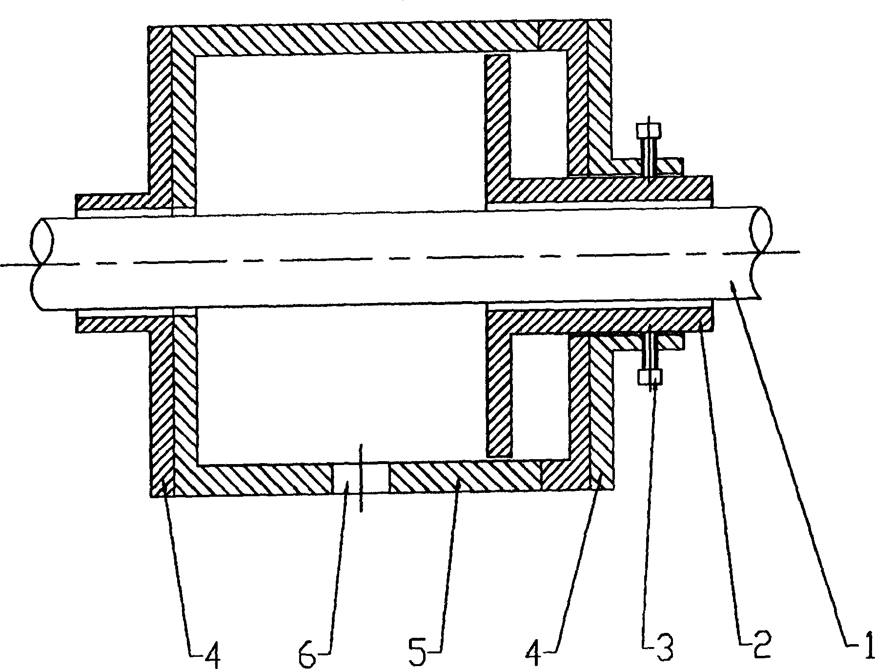
[0014] Embodiments of the present invention are further described below in conjunction with the accompanying drawings, including TE 011 The cylindrical resonant cavity housing 5 of the model cavity has an inner diameter of Ф150 mm to Ф220 mm and a length of 70 mm to 110 mm for electromagnetic waves of 2.45 GHz. There is a through hole 6 connected to the waveguide device in the circumferential direction of the cylindrical resonant cavity shell, cut-off waveguides 4 are set at both ends of the cylindrical resonant cavity shell, and a tuning piston 2 is installed at one end of the cylindrical resonant cavity cavity , the front end of the tuning piston is in the shape of a disc, and the extension part of the rear section is a hollow shaft with a small diameter. The hollow shaft of the extension part is slidingly arranged with the end hole of the resonant cavity shell, and the front end of the tuning piston extends into the cavity of the resonant cavity. The depth is 0-40mm, and th...


PUM


Abstract

The present invention relates to a kind of tunable plasma resonant cavity for PCVD optical fiber perform rod processing machine. The tunable plasma resonant cavity includes cylindrical resonant cavity casing and cut-off waveguides set on two ends of the casing, and features the tuning piston, which is set on one end of the cylindrical resonant cavity and has middle part with through hole and back end stretched beyond the casing. Setting the tuning piston can realize the matching between the waveguide device and the resonant cavity and the real-time control of energy coupling, raise the processing precision and efficiency of PCVD process, avoid the damage of microwave on the system devices and increase the service life of the plasma resonant cavity microwave system. The present invention has stable field structure, no polarizing and degenerate mode, low loss and high Q and other features.

Description

technical field [0001] The invention relates to a tunable plasma resonant cavity used for a PCVD optical fiber preform processing machine tool, which is an improvement on the existing plasma resonant cavity. Background technique [0002] PCVD, or plasma chemical vapor deposition, is one of the main processes for processing optical fiber preforms. The processing mechanism of the PCVD process is the direct action of high-frequency microwaves on the reactant gas, causing rapid physical and chemical reactions to form pure silica or Doped silica is deposited directly in the glassy state on the inner wall of the quartz tube. The PCVD process has the characteristics of flexibility and precision, and the plasma resonator microwave system is the core part of the PCVD processing equipment. Plasma resonator microwave system consists of three parts: plasma resonator, microwave generator and waveguide device. The area emits high-frequency microwave energy to complete the PCVD process. ...

Claims


Application Information

Patent Timeline
IPC IPC(8): C23C16/513C23C16/52H05H1/34
Inventor 孙建华李震宇刘善沛
Owner YANGTZE OPTICAL FIBRE & CABLE CO LTD
Learn More