

Method of directly liquifying coal
A technology for direct liquefaction of coal and pulverized coal, which is applied in the preparation of liquid hydrocarbon mixtures and the petroleum industry, can solve problems such as increased equipment investment, and achieve the effects of avoiding secondary decomposition, improving oil yield and timely separation.
- Summary
- Abstract
- Description
- Claims
- Application Information
AI Technical Summary
Problems solved by technology
Method used
Image

Examples
Embodiment Construction
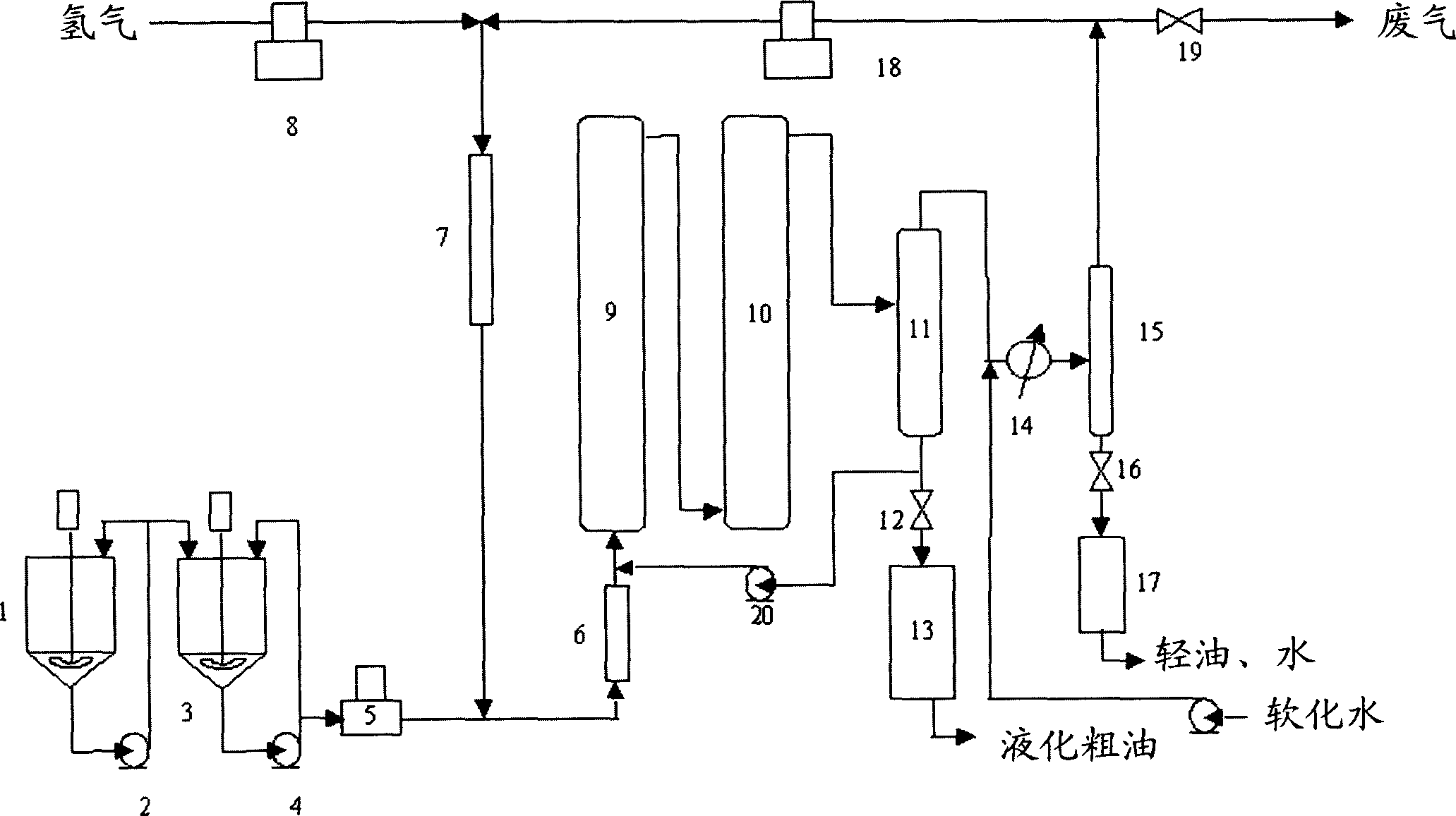
[0020] The method provided by the present invention will be further described below in conjunction with the accompanying drawings, but the present invention is not limited thereto.
[0021] Such as figure 1 As shown, the coal slurry preparation is carried out in the coal slurry preparation tank 1, and the solvent, dry coal powder, catalyst and co-catalyst are weighed and then added to the coal slurry preparation tank 1 in proportion. The prepared coal slurry is delivered to the coal slurry metering tank 3 through the low-pressure coal slurry circulating pump 2 . The temperature of the coal slurry preparation tank and coal slurry metering tank is generally controlled at 50-170°C. The coal slurry preparation tank is equipped with stirring equipment and coal slurry circulation pump 2, and the coal slurry metering tank may not have stirring equipment, but it should be equipped with coal slurry circulation pump 4.
[0022] The coal slurry in the coal slurry metering tank is deliv...
PUM
 Abstract
Description
Claims
Application Information