Feedback type organic waste matter biological fermentation device

A technology of organic waste and biological fermentation, which is applied in the fields of organic fertilizers, fertilization devices, preparation of organic fertilizers, etc., can solve the problems of difficulty in maintaining the temperature of the reactor, low processing efficiency, large area/volume, etc., and achieves additional output. High value, no secondary pollution, good safety effect

Inactive Publication Date: 2006-11-29
魏晓路
View PDF0 Cites 19 Cited by
  • Summary
  • Abstract
  • Description
  • Claims
  • Application Information

AI Technical Summary

Problems solved by technology

Disadvantages: 1. Solids are easy to settle at the bottom of the tank, affecting the effective volume of the reactor, and the efficiency is low; 2. The reflux of solids and microorganisms is required as the inoculum; 3. Due to the relatively large area / volume of the reactor, the reactor Difficulty maintaining a consistent temperature; 4 prone to thick crusts
Disadvantages: low treatment efficiency, high suspended solids content in effluent, poor impact load resistance, and low process stability;
[0009] UASB is a new process successfully researched by Lettinga et al. from 1974 to 1978. It is an improved version of USR. This digester is suitable for treating soluble wastewater and requires lower suspended solids content. Disadvantages of this process: 1. Need to install three-phase Separator; 2. The feed water can only contain low concentration of suspended solids; 3. An effective water distributor is needed to make the feed evenly distributed at the bottom of the digester; 4. When the impact load or the suspended solids content in the feed Increased, and when encountering excessive toxic substances, it will cause sludge loss, stop the reaction, and require a higher management level
Used for the treatment of high-concentration and high-suspended solid wastewater, which is prone to clogging

Method used


Image

  • Feedback type organic waste matter biological fermentation device

Examples


Embodiment Construction

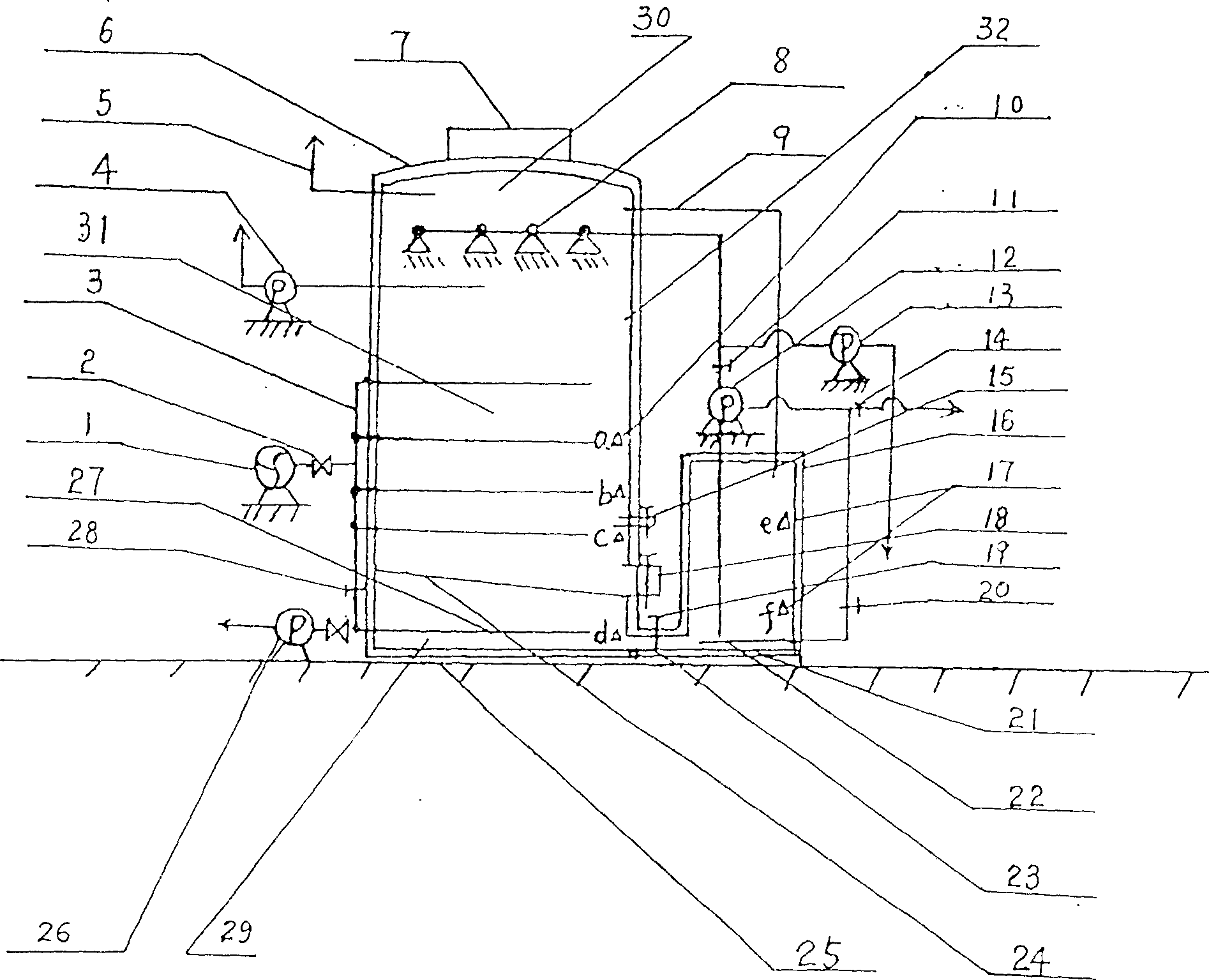
[0020] Such as figure 1 As shown, the present invention includes a reaction vessel 32, the upper end of the reaction vessel 32 is provided with a feed inlet 7, and a solid-liquid separation grid 24 is provided in the reactor, and the solid-liquid separation grid 24 separates the inside of the reactor 32 up and down. Separated into a reaction chamber and a liquid collection chamber 29, the upper part of the reaction chamber is an air chamber area 30, and the lower part is a reaction area 31. An aeration air distribution pipe 3 is provided at the upper reaction area of ​​the solid-liquid separation grid 24, and in the air chamber area Below the 30 is provided with the spray head 8 for regulating the circulation of the bacterial liquid, and outside the reaction vessel is provided with a buffer storage tank 16 for the return flow of the bacterial liquid. The buffer storage tank 16 communicates with the bacteria liquid circulation regulating spray head 8 through the bacterial liqui...


PUM


Abstract

The invention relates to the feedback biology ferment device of organic waste matter. It comprises the feed-in mouths on the top of the reacting room. The solid-liquid separating gridiron is mounted in the reactor, solid-liquid separating gridiron vertically separates the reactor into the reacting chamber and collecting liquid chamber. Gas section is on the top of reacting chamber and reacting section is on the bottom of it. The insolating gas cloth trachea is mounted on the reacting section on the solid-liquid separating gridiron, the bacterium liquid circumfluence jar is mounted on the gas room section, the bacterium liquid circumfluence cushioning storing jar is mounted outside of the reacting setting, the bacterium liquid circumfluence cushioning storing jar connects the collecting liquid room in the reactor, the bacterium liquid circumfluence cushioning jar connects the bacterium liquid circling adopting spray through the one route out mouth of the bacterium liquid circling pump. The invention is using two-phase dry ferment technique to reach a high rate of degradation reaction.

Description

Technical field [0001] The invention relates to a kind of biochemical degradation treatment of organic waste such as urban domestic waste, agricultural waste, kitchen waste, food industry waste, etc., so that it can be converted into clean energy biogas and active organic fertilizer that can be returned to the soil---- -- Biogas fertilizer equipment, especially a feedback type organic waste biological fermentation device, belongs to the field of environmental protection treatment technology. Background technique [0002] At present, the biochemical degradation of the above-mentioned organic waste technologies is mainly (1) organic matter aerobic composting technology, which utilizes the action of aerobic bacteria to degrade biochemical organic matter and convert it into humus (rich in refractory cellulose and lignin) and other organic matter that has not been completely degraded), carbon dioxide, ammonia and ash, etc., this mixture is collected and dried to become compost. ...

Claims


Application Information

Patent Timeline
Patent Type & Authority Applications(China)
IPC IPC(8): C12M1/107C05F17/02
CPCY02W30/40
Inventor 魏晓路孙明浩
Owner 魏晓路
Why Eureka
Try Eureka