Air separation system for recycling cold energy of liquified natural gas

A technology for separation of liquefied natural gas and air, which is applied in the direction of cold treatment separation, liquefaction, refrigeration and liquefaction, etc., can solve the problems of increased energy consumption and large energy consumption, and achieve the effect of compact structure, low cost, and reduced low-temperature pollution

Active Publication Date: 2006-12-06
福建智舟技术有限公司
View PDF0 Cites 30 Cited by
  • Summary
  • Abstract
  • Description
  • Claims
  • Application Information

AI Technical Summary

Problems solved by technology

However, the common air separation system consumes a lot of energy, especially when it is used to produce liquid gas, the energy consumption will increase exponentially

Method used


Image

  • Air separation system for recycling cold energy of liquified natural gas
  • Air separation system for recycling cold energy of liquified natural gas

Examples


Embodiment approach 1

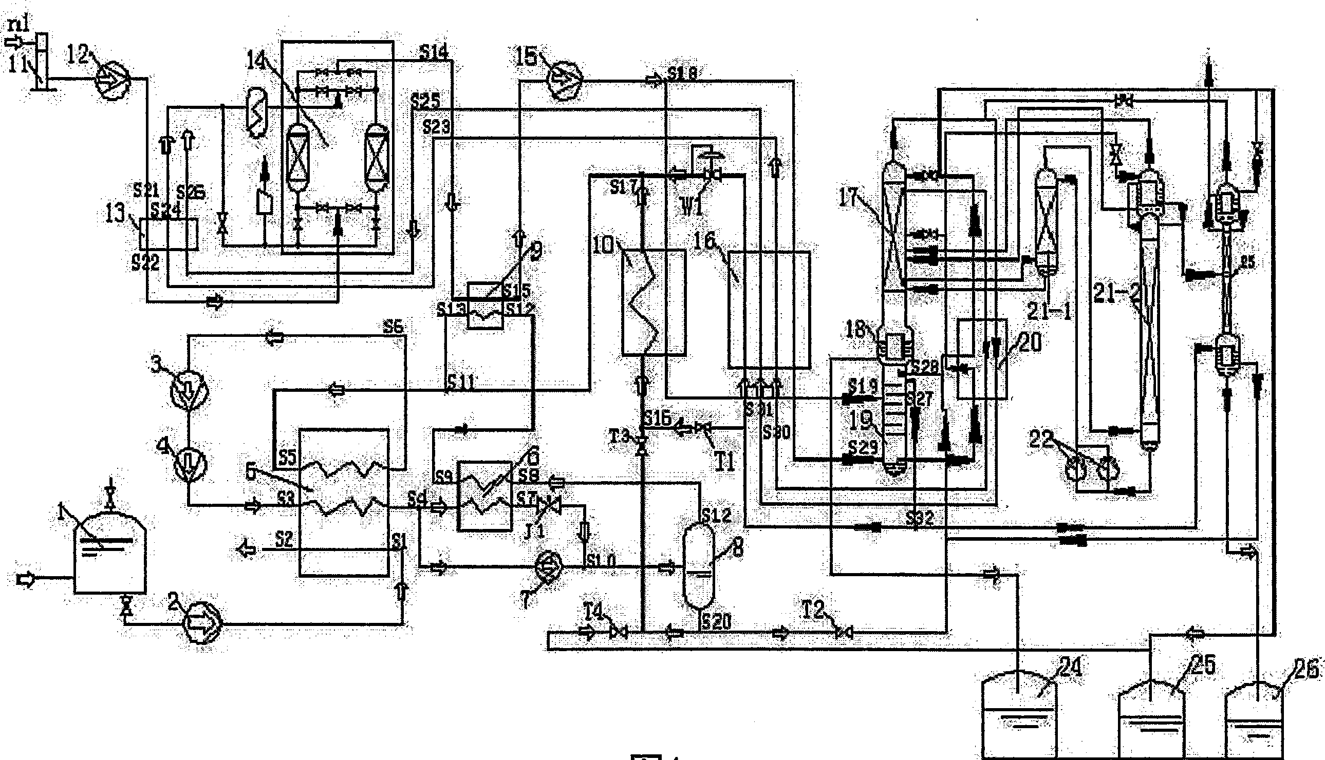
[0017] The first air separation system of the present invention specifically comprises a nitrogen refrigeration cycle device for precooling with liquefied natural gas cold energy, an air liquefaction separation device, an air cooler 9 and an air liquefaction device for connecting the nitrogen refrigeration cycle device and the air liquefaction separation device Device 10, a set of valves and connecting pipelines required for start-up and normal operation, wherein:

[0018] 1.1 The air cooler 9 is provided with a medium-pressure circulating nitrogen heat exchange channel S12→S13 and a raw material air heat exchange channel S14→S15, and the air liquefier 10 is provided with a medium-pressure liquid nitrogen heat exchange channel S16→S17 and Raw material air heat exchange channel S18→S19;

[0019] The nitrogen refrigeration cycle device described in 1.2 includes a liquefied natural gas storage tank 1, a liquefied natural gas booster pump 2, a low-temperature nitrogen cycle booste...

Embodiment approach 2

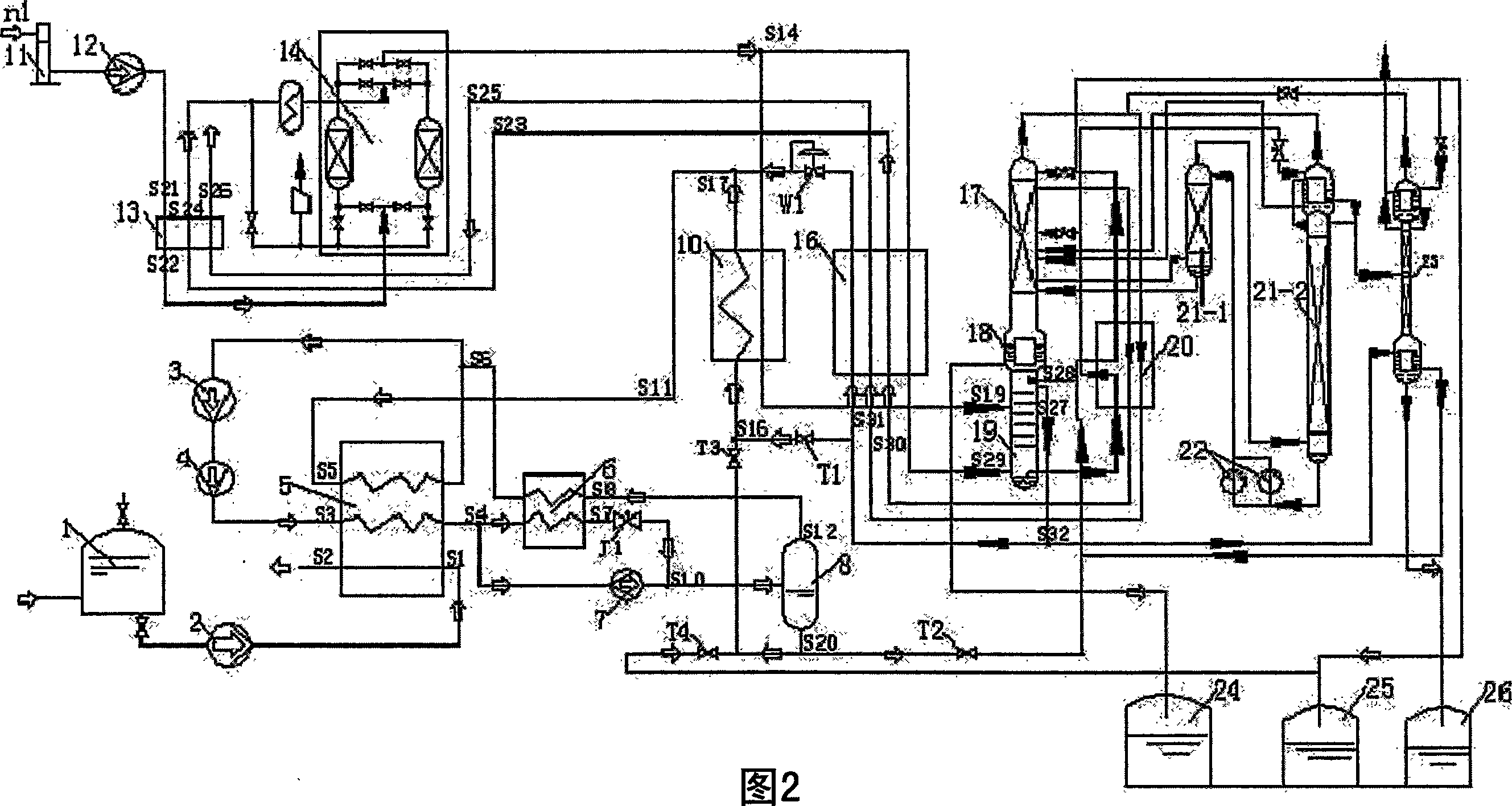
[0034] On the basis of Embodiment 1, other things remain unchanged, the air cooler 9 and the low-temperature air compressor 15 are omitted, the nodes S6 and S9 are combined into node S6; the nodes S14 and S18 are combined into node S14.

[0035] The working principle of this air separation system is:

[0036] (1) The flow process of the nitrogen refrigeration cycle: when the device starts, close the vent valve T2, T4, open the vent valve T1, T3. The nitrogen of 600KPa is drawn from the upper part S27 of the lower tower 19 of the air separation system, and enters the nitrogen through the vent valve T1 The refrigeration cycle system enters the air liquefier 10 (S16→S17) to exchange heat with the raw material air from the molecular sieve 4 (S14→S19), and then enters the liquefied natural gas heat exchanger 5 (S5→S6) to exchange heat with the liquefied natural gas ( S1→S2) to obtain the cooling capacity, the temperature drops to -120℃~-130℃, enters the nitrogen booster 3 to pressu...


PUM


Abstract

The present invention provides an air separation system capable of recovering cold energy of liquefied natural gas and using it to produce liquid oxygen, liquid nitrogen and liquid argon. Said system includes nitrogen gas refrigeration circulation device, air cooling device and air separation device, in which the nitrogen gas refrigeration circulation device includes liquefied natural gas beat exchanger and gas-liquid separator, the liquefied natural gas heat exchanger can be used for isolating the cold energy of liquefied natural gas and exchanging it to the nitrogen gas in nitrogen gas refrigeration circulation device, the gas-liquid separator can be used for separating the nitrogen gas undergone the process of heat exchange by means of liquefied natural gas heat exchanger into gas nitrogen gas and liquid nitrogen gas, said liquid nitrogen gas after which is undergone the process of cold energy exchange with raw material air is combined with gas nitrogen gas and can be again fed into the liquefied natural gas heat exchanger.

Description

technical field [0001] The invention relates to an air separation system for recovering the cold energy of liquefied natural gas. technical background [0002] Liquefied natural gas (LNG) is a high-quality energy source, featuring high calorific value, cleanliness, and low combustion pollution, and contains a large amount of high-grade low-temperature cooling capacity (the temperature of LNG after the high-pressure pump at the LNG station is generally -150 ° C ~ -160 ° C ). When liquefied natural gas is vaporized, sea water is usually used to absorb this part of the cold, and then the sea water is discharged into the sea, which not only wastes a lot of cold, but also causes low-temperature pollution in local sea areas, so how to recover and rationally use this considerable cold Quantity has become a subject that people are very concerned about and explored when using liquefied natural gas (LNG). [0003] The air separation system uses air as the raw material to separate ox...

Claims


Application Information

Patent Timeline
Patent Type & Authority Applications(China)
IPC IPC(8): F25J3/02
CPCF25J3/0406F25J3/04054F25J3/04181F25J3/04193F25J3/04412F25J3/04157F25J3/04703F25J3/04357F25J3/04266F25J3/04727F25J2205/70F25J3/04224F25J3/04678F25J2235/58
Inventor 林福粦
Owner 福建智舟技术有限公司
Why Eureka
Try Eureka