Ultra sensitive in-situ magnetometer system

A magnetometer and in-situ technology, which is applied in the field of ultra-sensitive in-situ magnetometer systems, can solve the problems that the characteristics of the magnetic film cannot be measured, the magnetic moment of the film cannot be monitored, and the magnetic properties cannot be checked.

Inactive Publication Date: 2006-12-06
FEMTONIS
View PDF0 Cites 4 Cited by
  • Summary
  • Abstract
  • Description
  • Claims
  • Application Information

AI Technical Summary

Problems solved by technology

[0011] However, the conventional system can only monitor the magnetic moment of the film after the film is deposited, so there is a problem that the magnetic moment of the film cannot be monitored during film deposition.
[0012] In addition, conventional monitoring systems must perform measurements after the film is deposited and the vacuum is broken, causing the film to oxidize and produce measurements only after the film is deposited
[0013] Some traditional monitoring systems can take measurements without breaking the vacuum, but still have the problem of only producing measurements after the film has been deposited
[0014] In addition, conventional monitoring systems can measure the characteristics of magnetic films with several angstrom precision, but cannot measure the characteristics of magnetic films with sub-angstrom precision, so there is a magnetic property obtained from the process of depositing ultra-thin films that cannot be checked Shortcomings

Method used


Image

  • Ultra sensitive in-situ magnetometer system
  • Ultra sensitive in-situ magnetometer system
  • Ultra sensitive in-situ magnetometer system

Examples


Embodiment 1

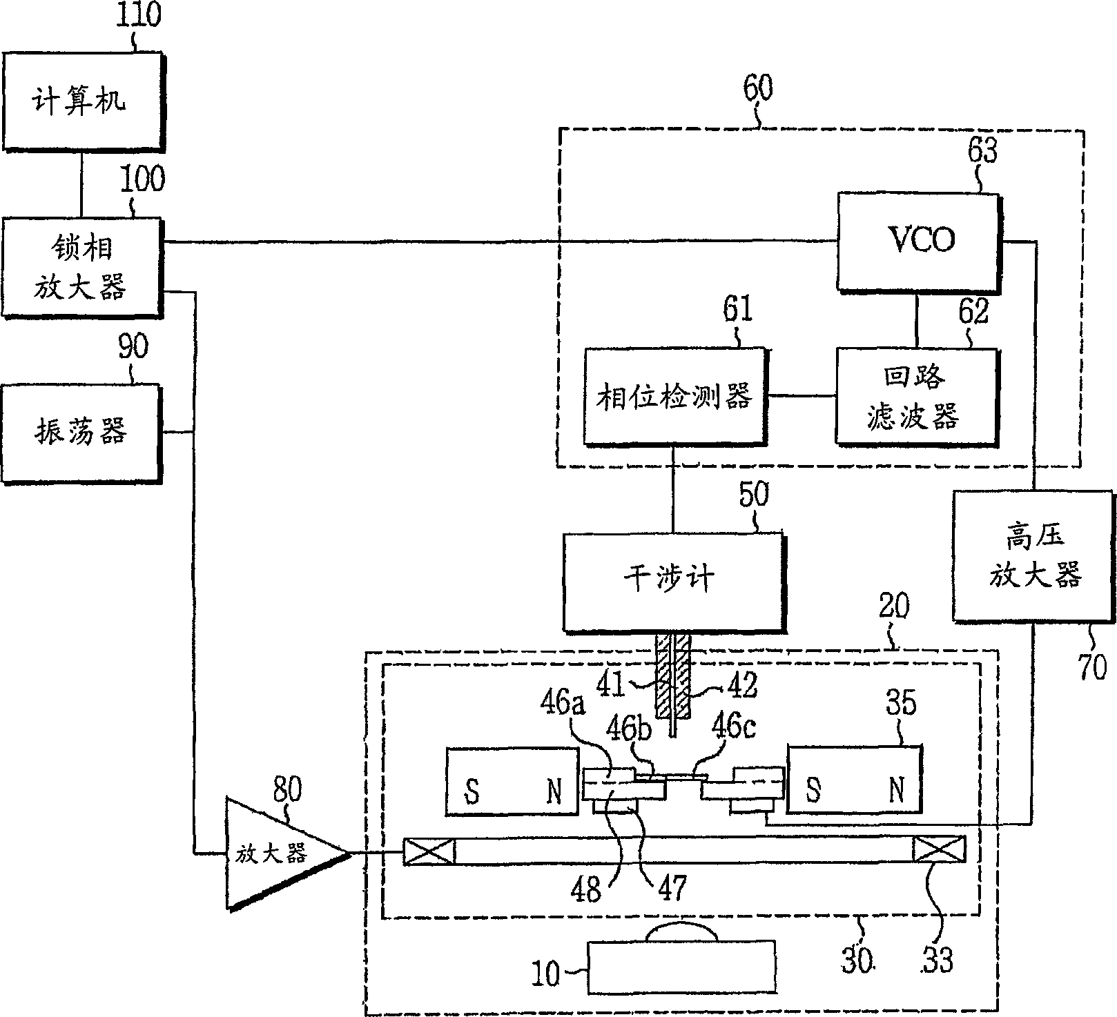
[0032] Now, an ultrasensitive in situ magnetometer system according to the present invention will be described.

[0033] like figure 1 As shown, the system according to the present invention includes a deposition source 10, a deposition head 30, an interferometer 50, a phase-locked loop (PLL) 60, a high voltage amplifier 70, a power amplifier 80, an oscillator 90, a lock-in amplifier (lock-in amplifier) 100 and computer 110. The PLL 60 includes three sections of a phase detector 61 , a loop filter 62 , and a voltage controlled oscillator (VCO) 63 .

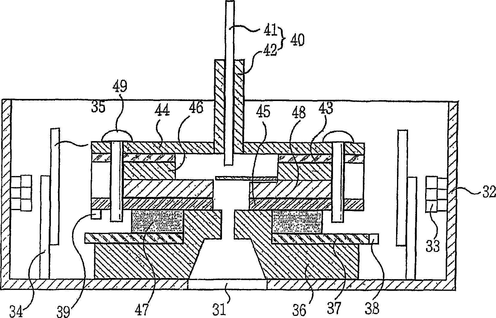
[0034] First, a deposition source 10 and a deposition head 30 are installed in an ultra high vacuum (UHV) chamber 20 . The deposition source 10 functions to supply magnetic atoms to the lower surface of a cantilever paddle 46 c of a cantilever chip 46 within the deposition head 30 . The deposition head 30 maintains the proper distance between the cleaving fiber 40 of the interferometer 50 and the surface of the cantilevered pad...

Embodiment 2

[0088] Figure 8 and 9 Another embodiment of an ultrasensitive in situ magnetometer system according to the present invention is shown. The ultrasensitive in situ magnetometer system includes: a deposition source 10; Atoms are deposited on the other surface of the cantilever paddle; an interferometer 50 for outputting an electrical signal by detecting the vibration of the cantilever paddle 46c; and the cantilever plate as described above. The ultrasensitive in situ magnetometer system also includes: a deposition head 30 for maintaining the proper distance between the cleaved fiber end of the interferometer 50 and the surface of the cantilever paddle 46c; a power amplifier 80a for adjusting the phase-locked The loop (PLL) 60 inputs the voltage and changes the amplitude of the voltage so as to output the changed amplitude; The phase difference between the signals is locked by feedback so that the phase difference is always equal to the phase value preset in the PID (Proportio...


PUM


Abstract

The present invention relates to an ultra sensitive in-situ magnetometer system, and more particularly to an ultra sensitive in-situ magnetometer system that can in-situ monitor a magnetic moment of a magnetic thin film with sub-monolayer precision while depositing and growing the magnetic thin film in an ultra high vacuum (UHV) chamber.

Description

technical field [0001] The present invention relates to an ultrasensitive in situ magnetometer system, and more particularly, to the ability to in situ monitor magnetic films with sub-monolayer or higher Ultrasensitive in-situ magnetometer system for precise magnetic moments of magnetic thin films. Background technique [0002] Generally, a magnetic sensor for monitoring the magnetic moment of a magnetic thin film may be implemented using Hall effect, magnetoresistance effect, induction coil, superconducting quantum interference device (SQUID), and the like. A method of measuring a magnetic field using a magnetic sensor is used as a monitoring method. [0003] First, the method using the Hall effect utilizes the phenomenon that when a magnetic field is applied to a plate in which a current flows, an electromotive force is generated due to the generation of an electric field in a direction perpendicular to the direction of the current and the direction of the magnetic field....

Claims


Application Information

Patent Timeline
Patent Type & Authority Applications(China)
IPC IPC(8): G01R33/02
CPCG01R33/02G01R33/038G05B2219/37573
Inventor 闵同焄
Owner FEMTONIS
Why Eureka
Try Eureka