Circulating fluidized bed type high temperature hot blast stove system

A technology of circulating fluidized bed and high-temperature hot blast stove, which is applied in the direction of fluidized bed combustion equipment, fluid heater, combustion type, etc. It can solve the problems of small load adjustment range, dew point corrosion, unstable operation, etc., and save alloy steel , increase the degree of turbulence, and ensure the effect of air velocity

Inactive Publication Date: 2010-05-12
XI AN JIAOTONG UNIV
View PDF2 Cites 0 Cited by
  • Summary
  • Abstract
  • Description
  • Claims
  • Application Information

AI Technical Summary

Problems solved by technology

However, the serious disadvantage of the heat pipe hot blast stove is that the development and use of the heat pipe itself is not yet mature when the working temperature is above 300 ° C. Under the high temperature working condition, problems such as pipe burst, ash blocking, and dew point corrosion are prone to occur, which makes the heat pipe hot blast stove work at high temperature. The risk of burnout increases under certain conditions, and the heat exchange effect of the heat pipe cannot be realized, so the application of the product is limited
[0004] In particular, most of the existing coal-fired hot blast stoves use horizontal reciprocating furnaces and chain furnaces, which have disadvantages such as low thermal efficiency, short service life, and bulky volume: the temperature of the hot air generated is generally around 300°C, and the combustion efficiency is less than 50%. Single type of coal, mainly high-quality coal as heat source, poor adaptability of coal type; short service life, generally less than 3 years; expensive maintenance and operation costs; serious pollution, low desulfurization efficiency, nitrogen oxide emissions as high as 600-1000mg / Nm 3 ;The operation is unstable, the load adjustment range is small, the load should not be too low, etc.
These shortcomings make the existing hot blast stove far from meeting the requirements of industrial development

Method used


Image

  • Circulating fluidized bed type high temperature hot blast stove system
  • Circulating fluidized bed type high temperature hot blast stove system

Examples


Embodiment Construction

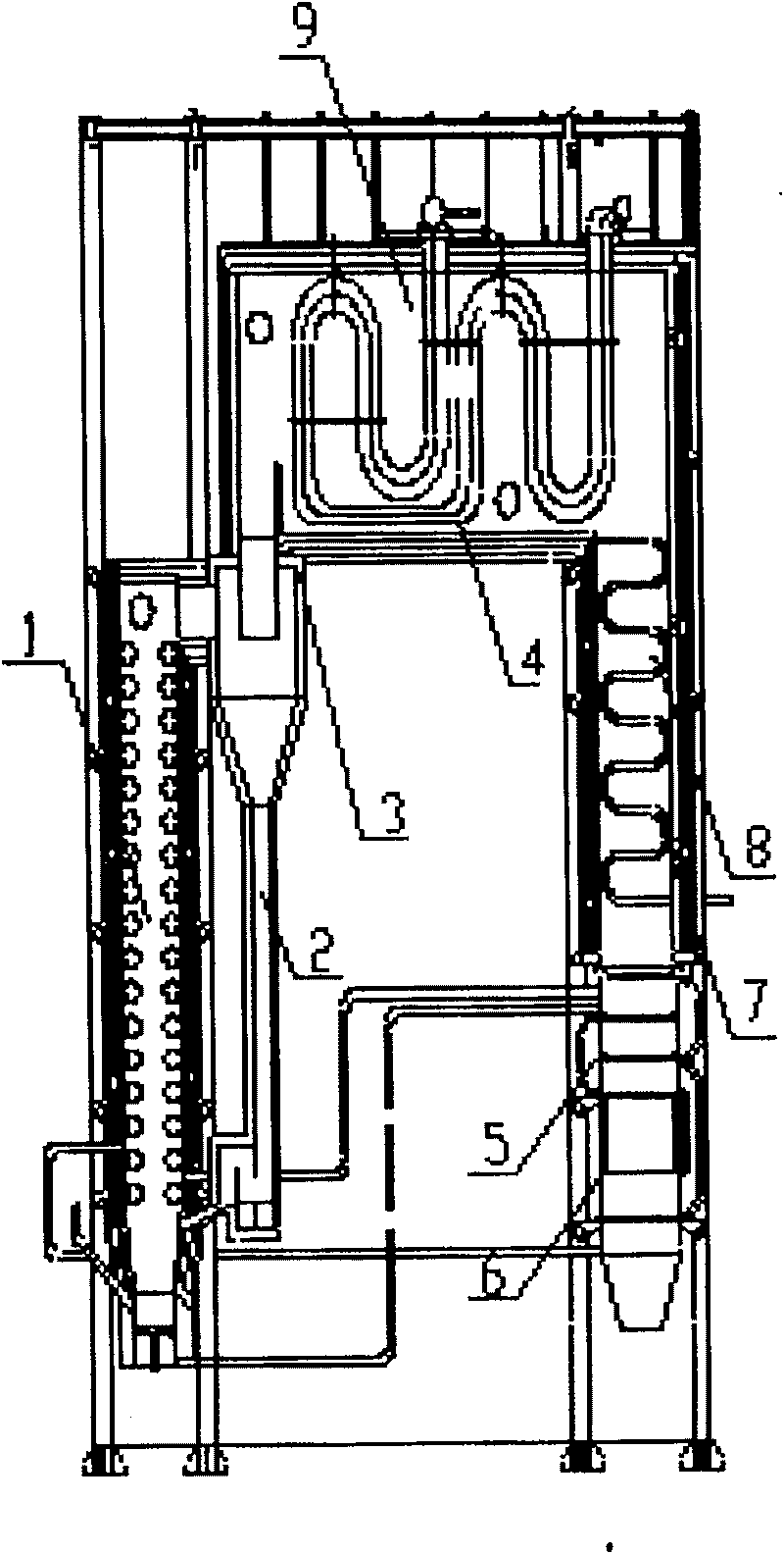
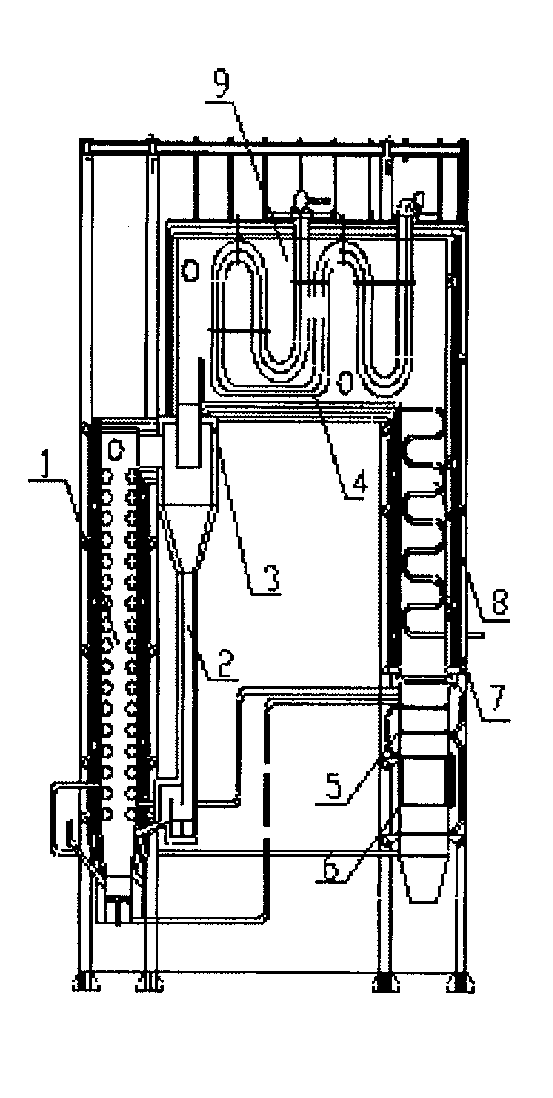
[0018] Referring to the accompanying drawings, a cyclone separator 3 is provided at the outlet of the circulating fluidized bed furnace 1 of the present invention, the bottom of the cyclone separator 3 is connected to the standpipe 2, and the top is connected to the horizontal flue 9, and a high-temperature flue is arranged in the horizontal flue 9. The heat exchanger 4, the end of the horizontal flue 9 is connected to the vertical tail flue 8, and the tail flue 8 is arranged in sequence from top to bottom with a low-temperature heat exchanger 7, a high-temperature air preheater 5, and a low-temperature air preheater 6 . The air distribution device adopts a hood-type air distribution plate to support the static fuel layer, maintain the stability of the fluidized bed layer, and increase the airflow resistance. The feeder adopts a flow sealing valve, which can ensure stable material flow, no gas backflow and controllable material flow, and can adapt to changes in boiler operatin...


PUM


Abstract

The invention relates to a cycle fluid bed high-temperature hot wind furnace, which comprises a hearth, a separator, a wind distributor, a material feeder, a high-low temperature exchanger and an airpreheat device. The invention is characterized in that: the hearth uses direct-current boiler type; the ascending tube uses three parallel tubes, to increase the heated area, avoid high-temperature smoke brushing the wall, and prolong the service life of wall; and guiding tail smoke into the secondary wind, to circulate the smoke and adjust the smoke temperature, strengthen the heat transmission and realize quick load adjustment; the air preheat device has a torsion plate as the turbolator to strengthen the heat transmission; and uses interlayer heater to confirm the clearness of hot wind; andcalculating each part, to select steel according to the temperature to reduce the consumption and refractory steel and reduce cost, based on confirmed strength.

Description

technical field [0001] The invention belongs to the field of industrial boilers, in particular to an industrial boiler system for providing high-temperature dry hot air. technical background [0002] Hot air stoves are widely used in the heating and dehumidification of agricultural products, food, pharmaceuticals, chemical raw materials, light and heavy industrial products, and can also be used for heating of various facilities and dehumidification of warehouses. With the rapid development of industry, the demand for hot blast stoves will increase, and the requirements for environmental protection and energy saving will also continue to increase. Therefore, energy-saving and environmentally friendly hot blast stoves have a huge market prospect. However, at present, domestic hot blast stove technology has not yet formed a complete theoretical system, and there is no unified standard and corresponding technical specifications. There are various product forms, and the overall s...

Claims


Application Information

Patent Timeline
Patent Type & Authority Patents(China)
IPC IPC(8): F23C10/00F24H3/00
Inventor 王树众李宁赵威王亮张钦明
Owner XI AN JIAOTONG UNIV
Why Eureka
Try Eureka