Method for accomplishing pseudo color reinforced metallographic microstructure based on digital image technology

A microstructure and digital image technology, which is applied in microscopes, image data processing, image data processing, etc., can solve the problems of unstable effects, environmental pollution, expensive equipment, etc., and achieve the effect of easy popularization, no pollution, and easy operation

Inactive Publication Date: 2006-12-13
NORTHWEST NORMAL UNIVERSITY
View PDF2 Cites 8 Cited by
  • Summary
  • Abstract
  • Description
  • Claims
  • Application Information

AI Technical Summary

Problems solved by technology
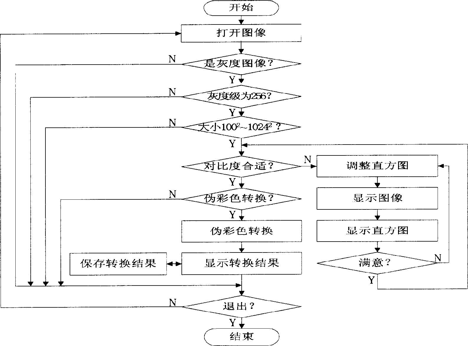
[0007] The purpose of the present invention is to overcome the existing color metallographic method or environmental pollution, expensive equipment; or cumbersome process, complex technology; or unstable effect, color confusion, difficult to be accepted and mastered by metal

Method used


Image

  • Method for accomplishing pseudo color reinforced metallographic microstructure based on digital image technology
  • Method for accomplishing pseudo color reinforced metallographic microstructure based on digital image technology
  • Method for accomplishing pseudo color reinforced metallographic microstructure based on digital image technology

Examples


Example Embodiment

[0055] Example 1: Figure 4a It is a grayscale image (500×) of the quenched structure of high-speed steel W18Cr4V. There are white massive carbides and white skeletal carbides (eutectic ledeburite) distributed on the gray martensite-retained austenite matrix. There are quenched troostite and quenched sorbite (eutectoid products of 6 phases) that are black clusters, among which the grayscale difference between martensite-retained austenite matrix and carbide is small, and it is difficult to distinguish by grayscale; Figure 4b Yes Figure 4a The pseudo-color image of , in which the massive and skeletal primary carbides are rendered in dark red, and the martensite-retained austenite is rendered in light red, with obvious color difference; the blue area is a black structure, in which the dark blue quenched Troostite and lake blue quenched sorbite are magically separated, and the orange dots are secondary carbides; martensite-retained austenite is a piece of red at a rough look, ...

Example Embodiment

[0056] Example 2: Figure 5a It is the grayscale image (500×) of the quenched and over-sintered structure of Cr12 steel. Black acicular coarse tempered martensite is distributed on the austenite matrix with gray coarse grains, and white massive granular carbides are deposited at the black grain boundaries. It is eutectic ledeburite produced by overburning; Figure 5b Figure 5a The pseudo-color image of , the coarse austenite grains delineated by the blue grain boundaries turn into an orange-red matrix, the distributed eutectic ledeburite carbides turn into dark red, and the carbides and austenite are separated by color; The distributed tempered martensite turns dark blue.

Example Embodiment

[0057] Example 3: Figure 6a It is the grayscale image (400×) of the quenched and tempered structure at the shrinkage porosity of cast steel ZG50. There are white lumps (quenching and heating) undissolved ferrite remaining on the gray tempered troostite matrix, and there are a large number of ( Unquenched) black agglomerate quenched troostite and white reticulated proeutectoid ferrite; Figure 6b Yes Figure 6a Pseudo-color image of tempered troostite turns lake blue, undissolved ferrite turns dark red, quenched troostite turns dark blue, and proeutectoid ferrite turns red or orange; tempered troostite turns red or orange; The solid and quenched troostite are clearly distinguished in the pseudo-color image.


PUM


Abstract

Disclosed is a method for enhancing metal phase microscopic structure with fake color. The method comprises designing a matching relation model of the metal phase gray grades versus fake colors; compiling a metal phase fake color system operated on computer; inputting the gray grades digital image of the metal phase microscopic structure into computer, selecting whether to perform gray histogram equalizing process according to the quality of the contrast of the original image gray grade; performing fake color conversion on the metal phase image with proper gray contrast, and forming and displaying the fake color digital image to distinguish and identify the metal phase microscopic structure.

Description

technical field [0001] The invention belongs to the technical field of metallographic analysis, and relates to a method for using digital image processing technology to convert the metallographic grayscale difference into a pseudo-color enhancement of the metallographic microstructure of the color tone difference. Phase pseudo-color system implementation. Background technique [0002] As we all know, metals are mostly composed of a variety of crystal materials (structures) with different types of crystal structures (phases). The microstructure analysis is generally carried out by observing the metal phases on the etched surface of metallographic samples and the morphology and grayscale of their tissue sections. identification. The surface of the metallographic sample must be ground and polished into a mirror surface, and then a suitable metallographic etchant is used to corrode the originally smooth surface into an uneven microscopic relief. , The grain boundary is most li...

Claims


Application Information

Patent Timeline
IPC IPC(8): G01N33/48G01N21/84G01B9/04G02B21/00G02B27/00G06T1/00G06K9/00G06F17/00
Inventor 厉树忠韩国才厉为刘进张锂张媛
Owner NORTHWEST NORMAL UNIVERSITY
Why Eureka
Try Eureka