Heat radiator

A heat dissipation device and heat dissipation fin technology, which is applied in the direction of indirect heat exchangers, heat exchange equipment, lighting and heating equipment, etc., can solve problems such as difficulty in meeting heat dissipation requirements, heat conduction of heat dissipation devices, and heat dissipation efficiency needs to be improved, so as to avoid partial Effects of hot spots, improved heat dissipation efficiency, and uniform heat distribution

Inactive Publication Date: 2006-12-13
HONG FU JIN PRECISION IND (SHENZHEN) CO LTD +1
View PDF1 Cites 19 Cited by
  • Summary
  • Abstract
  • Description
  • Claims
  • Application Information

AI Technical Summary

Problems solved by technology

However, even if the base is made of metal materials with strong thermal conductivity such as copper or aluminum, it is gradually difficult to meet the heat dissipation requirements of current high-frequency and high-speed electronic components. Therefore, the heat conduction and heat dissipation efficiency of the heat sink needs to be improved.

Method used


Image

  • Heat radiator
  • Heat radiator
  • Heat radiator

Examples


Embodiment approach

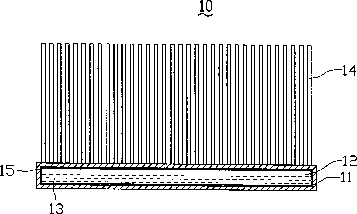
[0017] See figure 1 , The heat dissipation device 10 provided by the first embodiment includes a base 11 and a multi-media heat dissipation fin 14 extending on a surface of the base 11. The base 11 has a sealed hollow cavity 12 inside, and the hollow cavity 12 is filled with working Fluid 13, the working fluid 13 is added with nano-scale thermal conductive material particles.

[0018] The base 11 can be formed by two metal buckles hollowed out in the middle and welded together, and the hollow cavity 12 inside the base 11 is formed by buckling the hollowed out parts. After the hollow cavity 12 is evacuated, an appropriate amount of working fluid 13 is filled and then sealed. The volume of the working fluid 13 usually occupies 10 to 90% of the volume of the cavity 12. The working fluid 13 usually includes liquids such as water, ammonia, methanol, ethanol, hexanol, acetone, heptane and the like. Nano-scale thermal conductive material particles include nano-scale metal material powde...


PUM


Abstract

The invention relates to a heat emitter, which comprises: a base and several heat emission fins extending from one surface of base. Wherein, said base contains one sealing hollow chamber filled with working fluid; the working fluid is added with nanometer thermal conducive material particles; when the heat emitter works, the heat of heating electric element is transmitted to the base; the internal working fluid will be heated and vaporized, to adsorb the phase-change heat into gas; when the gas reaches one side of heat emission fin, it is cooled to be condensed into liquid to release heat; and the heat emission fin will transmit the heat to environment, to reduce the temperature heating electric element. Since the heat emission base uses phase-change heat transmission, and the working fluid is added with high-conductivity nanometer thermal conductive material particles, the heat emission efficiency is improved significantly.

Description

【Technical Field】 [0001] The present invention relates to a heat dissipation device, in particular to a heat dissipation device that is applied to heat dissipation of electronic components, has high heat dissipation efficiency, and is beneficial to the dense and miniaturized integrated circuits. 【Background technique】 [0002] In recent years, the rapid development of electronic technology, the high frequency and high speed of electronic components, and the density and miniaturization of integrated circuits have caused a sharp increase in the amount of heat generated by electronic components per unit volume. Therefore, a heat sink is attached to the electronic components to reduce the amount of time the electronic components work. The generated heat is transferred to the air to ensure stable operation of electronic components. [0003] Existing related heat dissipation device structures used to assist electronic components to dissipate heat can refer to US Patent No. 4,884,331 pu...

Claims


Application Information

Patent Timeline
Patent Type & Authority Applications(China)
IPC IPC(8): H05K7/20G12B15/02G06F1/20H01L23/36
CPCH01L23/467H01L2924/0002H01L23/427F28D15/0233F28F3/02H01L2924/00
Inventor 李欣和
Owner HONG FU JIN PRECISION IND (SHENZHEN) CO LTD
Why Eureka
Try Eureka