Multifunction heat syphon convection double circulation solar water heater

A multi-functional, thermosiphon technology, applied in the field of solar energy applications, to solve visual pollution, realize pressure-bearing operation, and easy to install

Inactive Publication Date: 2007-01-24
徐宝安
View PDF0 Cites 19 Cited by
  • Summary
  • Abstract
  • Description
  • Claims
  • Application Information

AI Technical Summary

Problems solved by technology

[0003] In order to overcome many problems of existing solar water heaters, a multifu

Method used


Image

  • Multifunction heat syphon convection double circulation solar water heater
  • Multifunction heat syphon convection double circulation solar water heater
  • Multifunction heat syphon convection double circulation solar water heater

Examples


no. 1 Embodiment

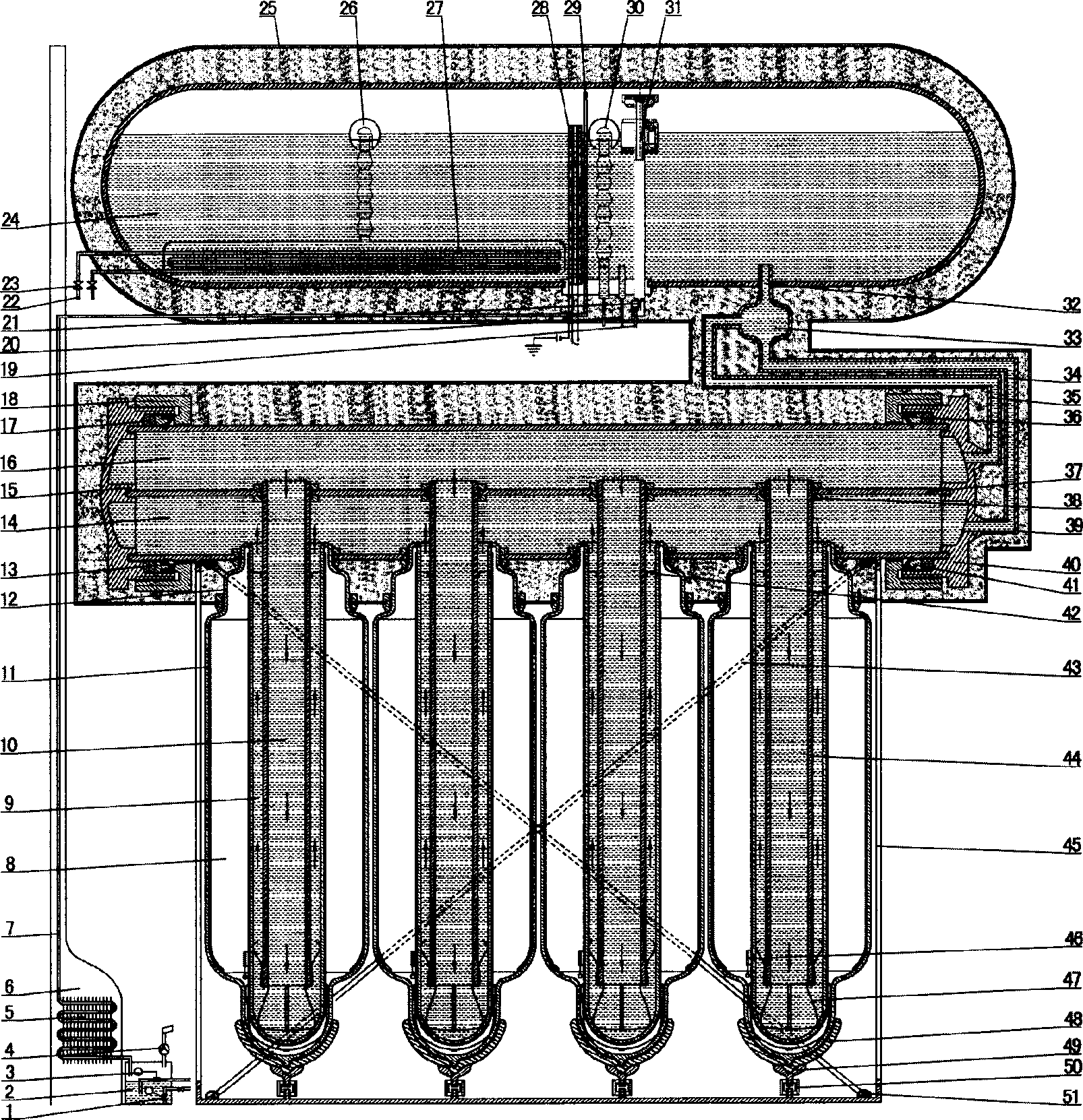
[0033] The first embodiment: the single-layer tube deflector 44 is suspended and fixedly installed in the lumen of the single-pass variable-diameter reflective concentrated solar vacuum heat collection tube 8 through the support clip 42 and the metal elastic clip 47, and the heat-collecting element is a single-pass variable-diameter Reflecting and concentrating solar energy vacuum heat collecting tubes are composed of 8 heat collecting elements, and the top of the heat collecting tubes is sealed and fixed on the header by a header opening sealing ring 38. The two ends of the header frame are a locking head device composed of a sealing ring 17, a pipe plug 15, a support ring 41, a locking expansion ring 36, a tightening device 18, and a header 40 of the header. In the water tank 24, a floating control pressure-bearing and non-pressure-bearing automatic switchover valve 31 is installed, which can realize pressure-bearing and non-pressure-bearing automatic conversion. The floating...

no. 2 Embodiment

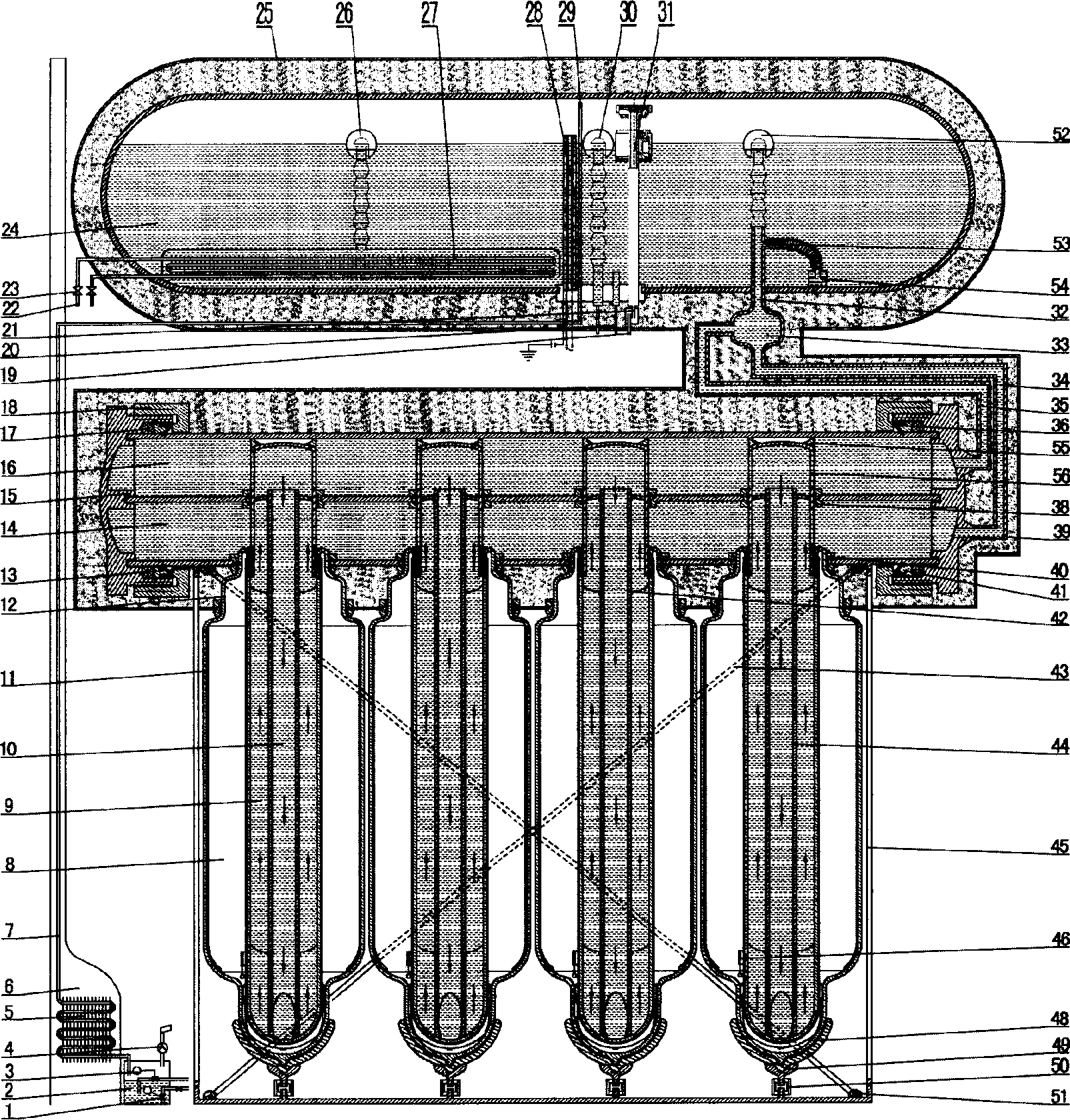
[0035] The second embodiment: the single-layer pipe deflector 44 is inserted and fixedly installed in the lumen of the single-pass variable-diameter reflective concentrating solar vacuum heat collection tube 8 through the oblique opening of the support card 42, and the single-pass variable-diameter reflective concentrating solar vacuum collector A pressure balance device 56 is connected to the top of the heat pipe 8, and a suction cap 55 is installed on the pressure balance device 56, which can realize the pressure-bearing operation of the vacuum heat collecting tube. The floating type fluid discharge pipe 52 is connected and fixed on the float, and the discharge port is below the water surface, and the fluid supply pipe 54 makes its water intake at the bottom of the water tank 24 through the counterweight device. Cold water is taken from the bottom of the water tank 24 through the fluid supply pipe 54, and the water is poured into the water supply pipe 35, the return pipe 34 a...

no. 3 Embodiment

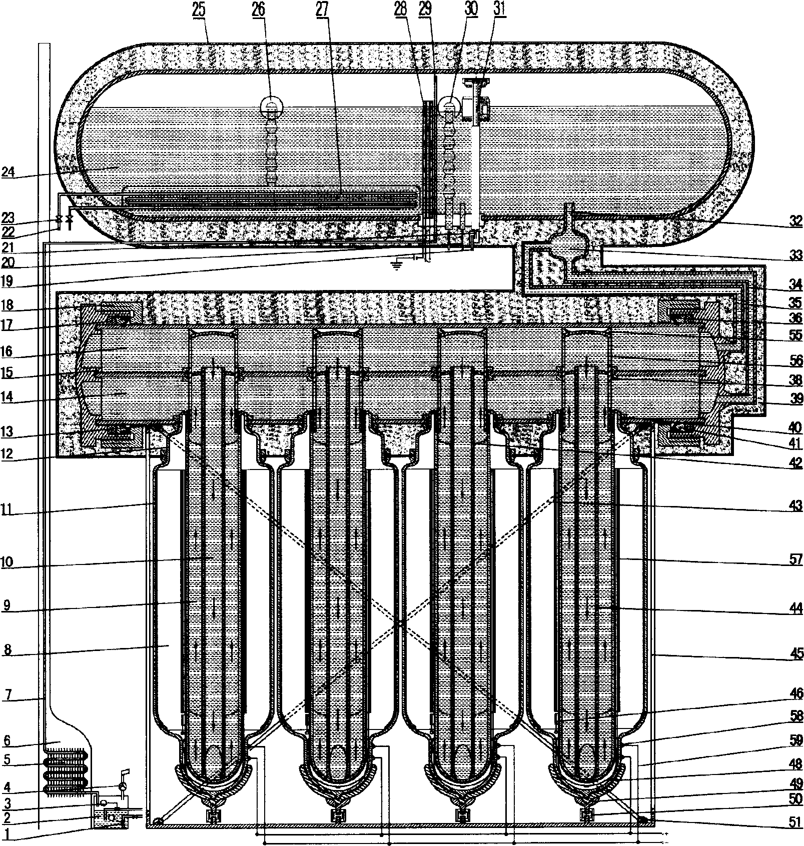
[0036] Embodiment 3: The single-layer tube deflector 44 is inserted and fixedly installed in the lumen of the single-pass variable-diameter reflective concentrating solar vacuum heat collection tube 8 through the oblique opening of the support card 42, and the single-pass variable-diameter reflective concentrating solar vacuum collector The heat pipe 8 is provided with a photovoltaic cell 57, and a wire 59 is drawn out through an electrical connection point 58 of the electrode heat-absorbing film. Others are the same as the first embodiment.


PUM


Abstract

The solar water heater is composed of solar energy heat collection device, multifunctional water storage installation, water circulated connecting insulated pipefittings, thermosiphon convective dual cycle plant, unit for feeding and catching water, and air inlet and exhaust unit. Thermosiphon convective dual cycle plant is composed of feed liquid pipe and drainpipe, liquid return pipe, liquid supply pipe, float type discharge pipe, and supply pipe of bottom liquid on throttle three way valve. Through pipes, thermosiphon convective dual cycle plant is installed between multifunctional water storage and solar energy heat collection device. Attaching unit for increasing function of multifunctional thermosiphon convective dual cycle solar water heater is installed on water circulated connecting insulated pipefitting.

Description

technical field [0001] The invention relates to a multifunctional thermosiphon convection double-circulation solar water heater, which belongs to the field of solar energy applications. Background technique [0002] The current solar water heater has a single function and poor thermal cycle effect. It often has the problem of serious scaling on the heat exchange surface of the vacuum heat collecting tube wall, which reduces the thermal efficiency of the solar water heater, and there is a problem of a single pipe rupture and water leakage that paralyzes the entire system. Pressure-bearing operation is severely restricted by the installation location, and the visual effect after installation is not beautiful, which greatly restricts its application field and causes visual pollution to urban buildings. In addition, it has serious scaling and poor frost resistance. Realize effective blowdown, more can't realize that family is heated, and cause water heater to boil when sunlight ...

Claims


Application Information

Patent Timeline
IPC IPC(8): F24J2/00F24D15/00F24S23/70
CPCY02E10/40
Inventor 徐宝安
Owner 徐宝安
Why Eureka
Try Eureka