System and method for testing device unit of phase change storage

A technology of phase change memory and test system, applied in the field of micro-nano electronics, can solve the problem of no standard test system and so on

Active Publication Date: 2007-01-31
SHANGHAI INST OF MICROSYSTEM & INFORMATION TECH CHINESE ACAD OF SCI
View PDF0 Cites 15 Cited by
  • Summary
  • Abstract
  • Description
  • Claims
  • Application Information

AI Technical Summary

Problems solved by technology

[0005] Therefore, in order to promote the research progress of phase change memory, it is very important to characterize the electrical and storage performance of its device unit (such as threshold voltage and current, read / write / erase optimal operating parameters, fatigue characteristics, etc.), but due to the The change memory is still in the research and development stage, and there is no relevant standard test system at home and abroad. Therefore, the present invention intends to propose a set of phase change memory device unit test system

Method used


Image

  • System and method for testing device unit of phase change storage
  • System and method for testing device unit of phase change storage
  • System and method for testing device unit of phase change storage

Examples


Embodiment 1

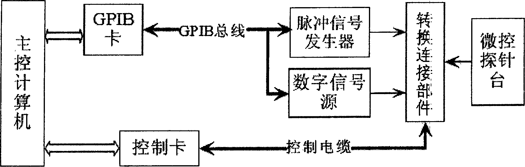
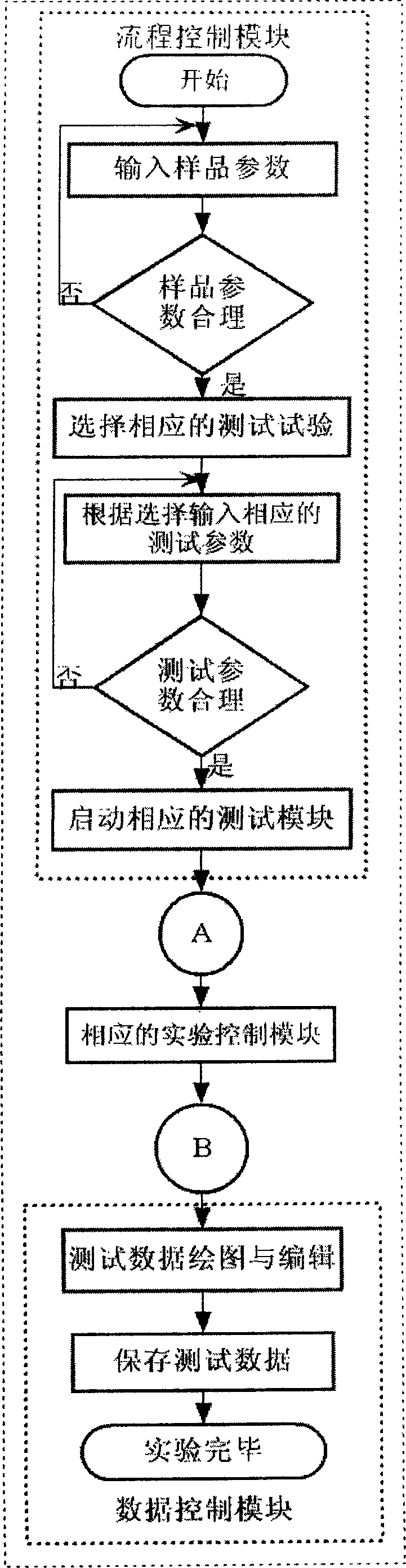
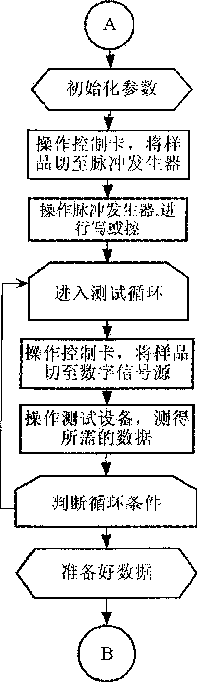
[0035] Image 6 It is a physical diagram of a phase change memory device unit test system. It is composed of control computer, control software, pulse signal generator, digital signal source, micro-control probe station and conversion connection parts and other hardware. Its operating software mainly includes current - Voltage test module, voltage-current test module, resistance and write pulse height test module, resistance and write pulse width test module, resistance and wipe pulse height test module, resistance and wipe pulse width test module, fatigue test module and other seven tests module. Among them, the model of the pulse signal generator is 81104A, and the manufacturer is Agilent Corporation of the United States. The pulse signal generator can generate pulse signals in single-channel and dual-channel modes. The pulse signal is characterized by: it can be a single pulse or a continuous pulse signal ;The shape characteristic of the pulse signal is a single shape or a...

Embodiment 2

[0038] Change the current-voltage test module used in embodiment 1 into a voltage-current test module, and the specific test parameters are as follows: the current test range is 0-1.75mA, and the step of current increase is 0.05mA, and all the other are the same as in embodiment 1. Record the corresponding current and voltage values ​​to get the voltage-current curve (such as Figure 9 shown). Depend on Figure 9 It is known that the critical phase change current and the critical phase change voltage for crystallization of the phase change material in the device unit are 0.1mA and 0.46V.

Embodiment 3

[0040] Change the current-voltage test module used in embodiment 1 into a resistance and write pulse high test module, and the specific test parameters are as follows: the current test range is 0.001-4.001mA, the step of the current increase is 0.1mA, and the width of the pulse current is 30ns, all the other are identical with embodiment 1, record corresponding electric current and resistance value and can obtain resistance-current curve (as Figure 10 shown). Depend on Figure 10 It is known that when the pulse current is lower than 3.0mA, the resistance is about 1000Ω, and the phase change film is still polycrystalline. Because the current is too low, the Joule heat provided is not enough to melt the film, so the amorphous state cannot be obtained. However, as the pulse current increases, the more Joule heat provided to the device unit, the greater the proportion of phase change material melting, so the proportion of the obtained amorphous state is also greater, and the res...


PUM


Abstract

The invention relates to phase change memory unit testing system and method. Its feature is that the testing system includes control computer, pulse signal generator, digital signal source, micro control probe table, and switch connecting part. The interface bus is used to connect main control computer with pulse signal generator and digital signal source. The middle three are connected by control cable of the control card. The main control computer is switched between pulse signal generator and digital signal source by micro control probe table whose two probes are respectively connected with up and down electrodes of the phase change memory to form a memory unit. Further more it can use operational module to realize seven kinds of detecting, such as current-voltage, voltage-current, resistance and writing pulse height, resistance and writing pulse width, resistance and swabbing pulse height, resistance and swabbing pulse width.

Description

technical field [0001] The invention relates to a performance testing system of a phase-change memory device unit, belonging to the technical field of micro-nano electronics. Background technique [0002] Phase change memory technology is based on Ovshinsky's proposal in the late 1960s (Phys. Rev. Lett., 21, 1450-1453, 1968) and early 1970s (Appl. Phys. Lett., 18, 254-257, 1971) The idea that the phase change film can be applied to the phase change storage medium is established, and it is a storage device with low price and stable performance. Phase-change memory can be made on a silicon wafer substrate, and its key materials are recordable phase-change films, heating electrode materials, heat insulating materials, and lead-out electrode materials. The basic principle of phase change memory is to use electric pulse signal to act on the device unit, so that the phase change material undergoes reversible phase transition between amorphous state and polycrystalline state. By d...

Claims


Application Information

Patent Timeline
Patent Type & Authority Applications(China)
IPC IPC(8): G11C29/56
Inventor 宋志棠刘波梁爽陈小刚封松林
Owner SHANGHAI INST OF MICROSYSTEM & INFORMATION TECH CHINESE ACAD OF SCI
Why Eureka
Try Eureka