
Polishing pad

A polishing pad and range technology, applied in the field of polishing pads, can solve the problems of uneven grinding pressure and repulsion, deviation of grinding amount, easy compression of foam pads, etc., and achieve the effect of reducing residual step height difference and high grinding speed.

Inactive Publication Date: 2007-01-31
NIHON MICRO COATING
View PDF1 Cites 24 Cited by
  • Summary
  • Abstract
  • Description
  • Claims
  • Application Information

AI Technical Summary

Problems solved by technology

[0012] However, because the foam pad is easy to compress and deform (high compressibility), after elastic deformation, it enters the concave part on the surface of the device, and in the process of flattening, it cuts into the concave part, resulting in residual step height difference
In addition, since the pore density inside the foam pad is not uniform, even if the surface of the pad is pressed against the surface of the wafer with a certain grinding pressure, the repulsion force of the pad to the grinding pressure is not uniform, and the surface of the pad cannot be made to act uniformly. Wafer surface cannot be ground uniformly over the entire wafer surface
Therefore, the amount of grinding at each point in the wafer surface deviates

Method used

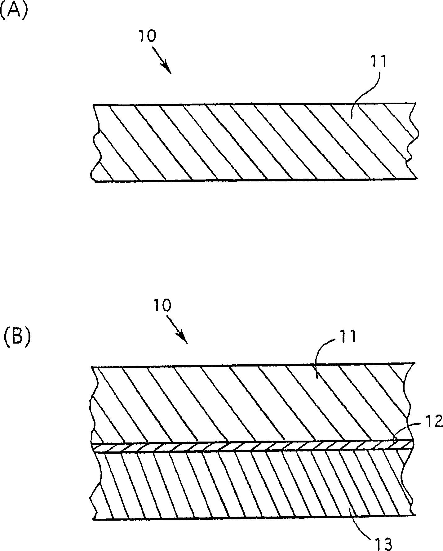
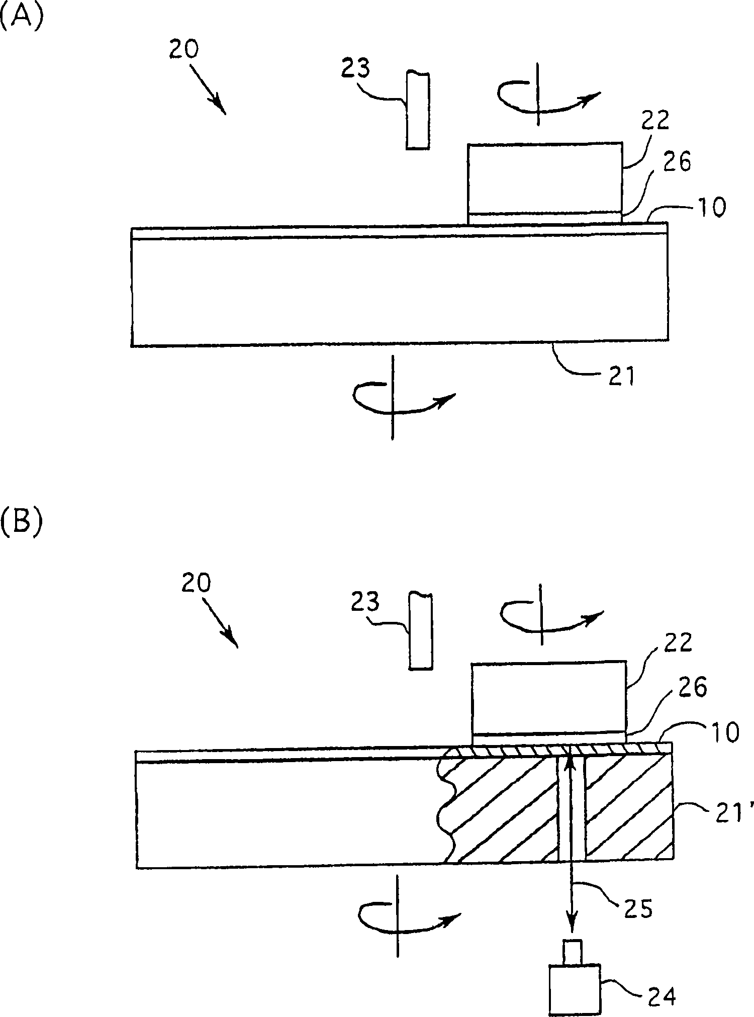
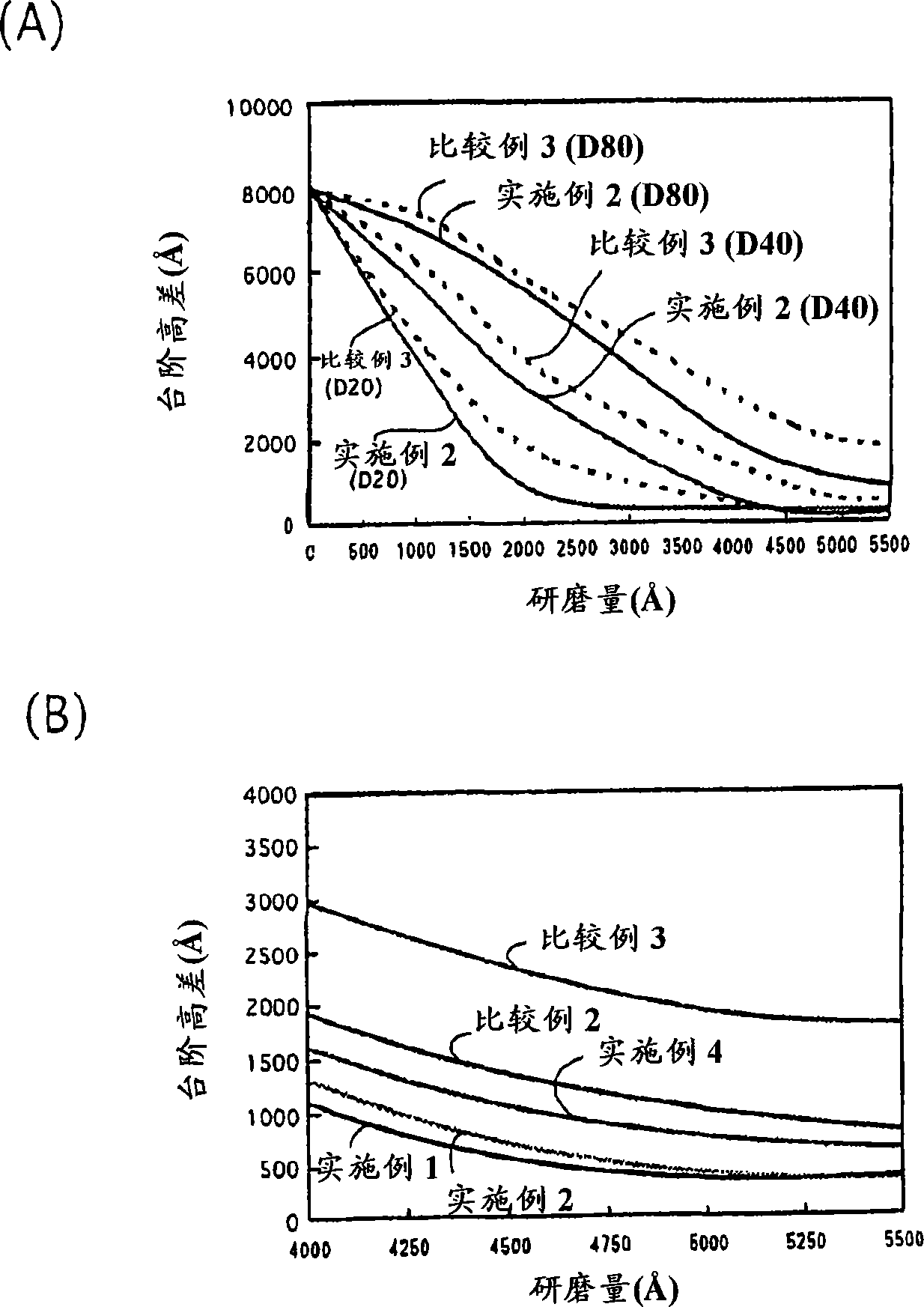

Image

  • Polishing pad
  • Polishing pad
  • Polishing pad

Examples


Embodiment 1

[0079] Using 3,3'-dichloro-4,4'diamino-diphenylmethane (26.5 parts) as a curing agent, add TDI (toluene diisocyanate)-based polyurethane preprepared with an average molecular weight of about 750. polymer (100 parts) to prepare a resin solution. This resin solution was poured into a metal mold, hardened in the mold, molded into a non-foam block, sliced ​​at a thickness of 1.5 mm, and made into a pad body having a Shore D hardness of 78.0 (measurement temperature: 23.0° C.), and then Use a lathe to do groove processing (groove shape: spiral, groove size: boss width 0.6mm / groove width 0.3mm, groove occupancy rate 33.3%) to the surface of the pad main body, use it as the grinding of embodiment 1 pad.

[0080] 0039

Embodiment 2

[0081] Using 3,3'-dichloro-4,4'diamino-diphenylmethane (26.5 parts) as a curing agent, add TDI-based polyurethane prepolymer (100 parts) with an average molecular weight of about 900 ) to prepare a resin solution. This resin solution was poured into a metal mold, hardened in the mold, molded into a non-foam block, sliced ​​at a thickness of 1.5 mm, and made into a pad body having a Shore D hardness of 75.0 (measurement temperature 23.0° C.), and then Use a lathe to groove the surface of the pad main body (groove shape: spiral, groove size: boss 0.6mm / groove 0.3mm, groove occupancy 33.3%), and use it as the polishing pad of Example 2.

[0082] 0040

Embodiment 3

[0083] Using 3,3'-dichloro-4,4'diamino-diphenylmethane (26.3 parts) as a hardening agent, add TDI-based polyurethane prepolymer (100 parts) with an average molecular weight of about 960 ) to prepare a resin solution. This resin solution was poured into a metal mold, hardened in the mold, molded into a non-foam block, and sliced ​​at a thickness of 1.5 mm to produce a pad main body with a Shore D hardness of 72.0 (measurement temperature 23.0° C.), followed by Use a lathe to groove the surface of the pad main body (groove shape: spiral, groove size: boss 0.6 mm / groove 0.3 mm, groove occupancy 33.3%), and use it as the polishing pad of Example 3.

[0084] 0041


PUM

PropertyMeasurementUnit
thicknessaaaaaaaaaa
thicknessaaaaaaaaaa
hardnessaaaaaaaaaa

Abstract

A polishing pad for planarizing the surface of a wafer has a planar main body of a non-foamed synthetic resin, having Shore D hardness of 66.0-78.5, preferably 70.0-78.5, or more preferably 70.0-78.0, compressibility of 4% or less or preferably 2% or less, and compression recovery rate of 50% or greater or preferably 70% or greater.

Description

technical field [0001] 0001 [0002] The present invention relates to the grinding pad used in the grinding of objects requiring high flatness on the surface such as semiconductor wafers, magnetic hard disk substrates, etc., and particularly relates to the wafer flattening (planarization) used in the manufacturing process of semiconductor devices abrasive pad. Background technique [0003] 0002 [0004] In the manufacturing process of semiconductor devices, the metal wiring layers that interconnect elements such as transistors, capacitors, and resistors are multilayered. Multilayer wiring is usually performed using photolithography and damassin. In photolithography, the wiring pattern is exposed, and then the metal wiring is laminated. However, when the interlayer insulating film is deposited on the metal wiring layer, etc., if there is a step difference on the surface of the device, and therefore the step is high If the unevenness of the device surface caused by the dif...

Claims


Application Information

Patent Timeline
Patent Type & Authority Applications(China)
IPC IPC(8): B24B37/00H01L21/304B24B37/20
CPCB24B37/24Y10T428/24628Y10T428/24669B24B37/00B24D11/00H01L21/304
Inventor 泉敏裕田村淳永峯拓也荒幡高志
Owner NIHON MICRO COATING
Learn More