New X ray tube, and fabricating method

An X-ray tube and X-ray technology, applied in the field of new X-ray tubes, can solve problems such as increasing system complexity, reducing X-ray flux utilization, and large distance from source to detector

Inactive Publication Date: 2007-02-21
SHENZHEN UNIV
View PDF0 Cites 16 Cited by
  • Summary
  • Abstract
  • Description
  • Claims
  • Application Information

AI Technical Summary

Problems solved by technology

However, the disadvantage of the F.Pfeiffer method is that the effective field of view of X-rays is limited and cannot be made very large; due to the increase of the source grating, the utilization rate of the X-ray flux is greatly reduced; the source grating is a kind of absorption grating, which requires It is very difficult to fabricate a sufficiently thick grating with a high-Z material; finally, the use of a source grating will increase the complexity of the system, making the distance from the source to the detector larger

Method used


Image

  • New X ray tube, and fabricating method
  • New X ray tube, and fabricating method
  • New X ray tube, and fabricating method

Examples


example

[0030] The second example of the present invention: electron beam scanning X-ray tube

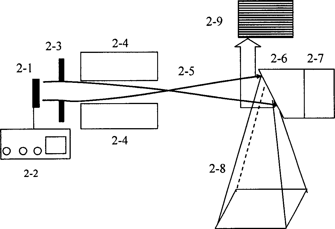
[0031] An electron beam scanning X-ray tube consists of an electron emitter, a grid, a focusing electrode, a deflection yoke, and a conventional unstructured anode (Fig. 7). The electron emitter (7-1) produces a small spot electron beam (7-5) under the control of the power supply and control system (7-8), which is accelerated by the grid (7-2) and focused by the focusing electrode before entering the deflection yoke (7-3A, 7-3B are horizontal deflection and vertical deflection respectively). The deflection system enables the small beam spot electron beam to scan quickly in two dimensions on the anode (7-6). The distribution of the electron beam on the anode forms a parallel line structure whose line width is the diameter of the beam spot. The scanning range is the X-ray beam line The effective area of ​​the emitter array. At any moment in the scanning process, only one point on the anode ...


PUM


Abstract

New type X ray tube is capable of generating X beam of rays with high spatial coherence, large dose, and large emission angle. Anode in extended electron beam or ion beam bomb structure, or structured electron beam or non-structured ion beam bomb is adopted in the invention to generate parallel-arranged linear array of emitter of X ray. Modes in structured electron or ion beam emitter, or structured grid, or electron or ion beam scan are adopted to realize emitter of X ray. Parallel-arranged periodic structure composed of high Z metal strips with narrow enough line width is adopted for structured anode. The disclosed X ray tube is workable under mode of continuous operation, or mode of pulse operation; and capable of outputting hard X ray or soft X ray. The invention is applicable to fundamental research in areas of biology, medical science, and material science etc. or in use for areas of disease diagnosis, industrial non-destructive inspection, online test etc.

Description

technical field [0001] The invention relates to a new type of X-ray tube, which uses a structured anode, or a structured electron beam or ion beam, or a structured emitter method to provide an X-ray beam with excellent spatial coherence, large dose, and wide emission angle, which can be used in X-ray tubes. Radiation phase contrast imaging and cone beam X-ray phase contrast CT can also be used in occasions that require high spatial coherence and dose of X-ray beams at the same time. Background technique [0002] Most of the most used X-ray sources in routine medical diagnosis and industrial non-destructive testing are based on the bombardment of metal anode targets by electron beams or ion beams. These X-ray sources mainly include electron emitters, focusing systems and anode targets in structure. The generated X-ray dose is large, the X-ray beam spot is also large, and its transverse coherence length is very small, almost negligible, so it does not have spatial coherence. ...

Claims


Application Information

Patent Timeline
Patent Type & Authority Applications(China)
IPC IPC(8): H01J35/00H01J35/08H01J35/06H01J35/14H05G1/00
CPCG21K2207/005H01J2235/086
Inventor 牛憨笨郭金川王凯歌杨勤劳
Owner SHENZHEN UNIV
Why Eureka
Try Eureka