Smog discharge continuous monitor system

A monitoring system and flue gas emission technology, applied in the direction of color/spectral characteristic measurement, instruments, analytical materials, etc., can solve the problems of reducing the trouble-free service time of the system, complex system structure, low reliability, etc., and achieve low engineering maintenance. , the system structure is simple, the effect of reducing maintenance

Active Publication Date: 2010-09-29
FOCUSED PHOTONICS
View PDF7 Cites 0 Cited by
  • Summary
  • Abstract
  • Description
  • Claims
  • Application Information

AI Technical Summary

Problems solved by technology

[0004] The above-mentioned monitoring systems all have the following major deficiencies: 1) the cost is high, and the diaphragm pump, dewatering device and condensing device all require corrosion resistance, and the price of the corrosion-resistant pump and condensing device is relatively high; 2) the service life is short, so the Both the diaphragm pump and the condensing device are moving parts, and they all work continuously, which reduces the trouble-free service time of the system; 3) the diaphragm pump and the condensing device both need power supply, and the power consumption is large; 4) the system structure is complex , there are many leaking and faulty devices, and the reliability is low

Method used


Image

  • Smog discharge continuous monitor system
  • Smog discharge continuous monitor system

Examples


Embodiment 1

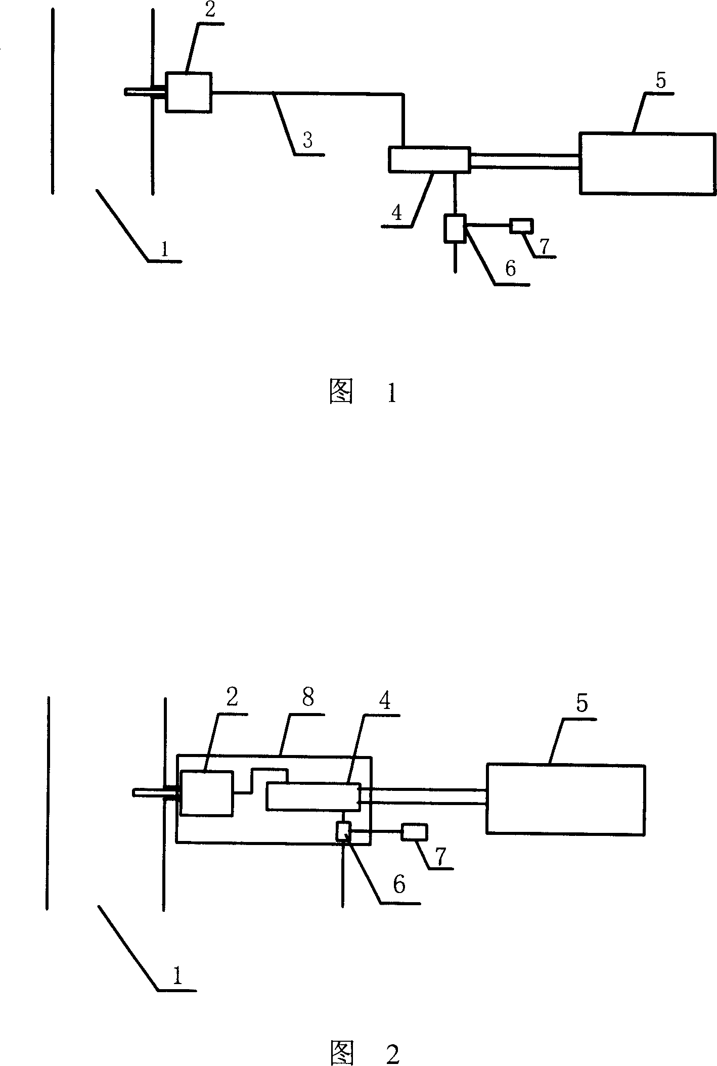
[0022] As shown in Figure 1, a flue gas emission continuous monitoring system is used for continuous monitoring of flue gas emission pollution sources, including sampling pretreatment device 2, heating pipeline 3, heating gas measuring chamber 4, measuring device 5 and gas extraction The device also includes a pressure sensor (not shown) mounted on the heated gas measuring chamber 4. The sampling pretreatment device 2 is installed on the measured gas pipeline 1 . Both ends of the heating line 3 are connected to the sampling pretreatment device 2 and the heating gas measuring chamber 4 . Described measuring device comprises a set of ultraviolet absorption spectrum analysis device 5, oxygen sensor (the present embodiment adopts zirconia sensor), and described ultraviolet absorption spectrum analysis device 5 is connected with heating gas measurement chamber by optical fiber, and described oxygen sensor (not shown Out) installed on the heating gas measuring chamber 4. The air e...

Embodiment 2

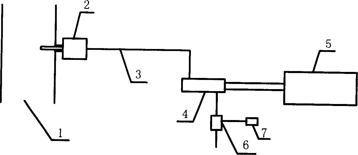
[0025] As shown in Figure 2, a continuous monitoring system for flue gas emission is used for continuous monitoring of flue gas emission pollution sources, including a sampling pretreatment device 2, a heating gas measurement chamber 4, a measuring device 5 and an extraction device. The sampling pretreatment device 2 is installed on the measured gas pipeline 1 . The sampling preprocessing device 2 is connected with the heating gas measuring chamber 4 and installed in a heating device 8 . The measuring device includes a set of ultraviolet absorption spectroscopic analysis device 5 and an oxygen sensor (a zirconia sensor is used in this embodiment), and the oxygen sensor is installed on the heating gas measuring chamber 3 . The air extraction device for extracting the flue gas in the pipeline under test is installed after the heating gas measurement chamber, including a jet device 6 and a gas source 7 (compressed air is used in this embodiment), and the jet device 6 is installed...


PUM


Abstract

This invention discloses one smoke continuous monitor system, which comprises the following parts: sampling device fixed on the measurement tube or channel; gas measurement chamber and measurement device; pump device to dry the smoke of the test device fixed on the gas measurement chamber; the said pump device comprises ejection device and the gas source connected.

Description

technical field [0001] The invention relates to a continuous monitoring system for flue gas emission, in particular to a continuous monitoring system (CEMS) for flue gas emission which does not need a water removal and condensation device, and uses a jet device to extract and analyze gas in a pipeline to be tested. Background technique [0002] A continuous monitoring system for flue gas emission, comprising a sampling device, a heat tracing pipeline, a water removal device, a condensing device, a diaphragm pump and a measuring device. The flue gas in the pipe to be tested is sampled by the sampling device, and then sent to the dehydration device through the heating pipeline to remove water, and then further dewatered by the condensing device, and then sent to the measuring device to measure various gases in the flue gas after passing through the condensing device Components such as sulfur dioxide, nitrogen monoxide, oxygen and other concentrations. Measuring devices usuall...

Claims


Application Information

Patent Timeline
Patent Type & Authority Patents(China)
IPC IPC(8): G01N35/00G01N21/33G01N27/12
Inventor 王健于志伟杨松杰
Owner FOCUSED PHOTONICS
Why Eureka
Try Eureka