

Planar antenna
一种平面天线、天线的技术,应用在天线、环形天线、谐振天线等方向,能够解决不是圆极化特性等问题,达到改善接收特性的效果
- Summary
- Abstract
- Description
- Claims
- Application Information
AI Technical Summary
Problems solved by technology
Method used
Image

Examples
no. 1 example
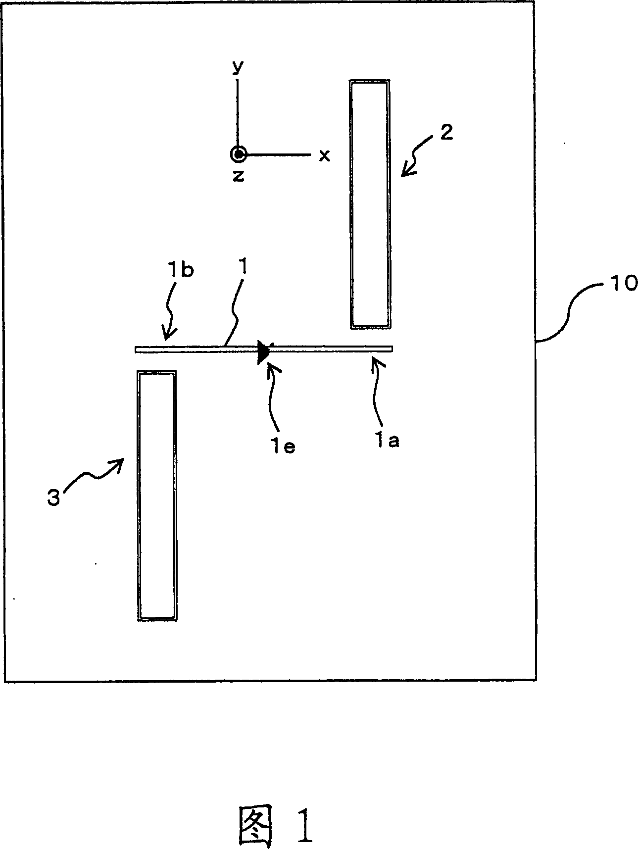
[0042]FIG. 1 is a schematic plan view showing the structure of a planar antenna according to a first embodiment of the present invention. In the planar antenna of FIG. 1, on a dielectric substrate (hereinafter, simply referred to as "dielectric" or "substrate") 10 made of, for example, glass or ceramics, a dipole antenna element (linear antenna element) 1 is formed, which The dipole antenna element is a linear antenna conductor supplied with power (feed) from the feed point 1e. The substrate can be divided into two regions (sections) with the dipole antenna element 1 as a boundary. In one of these two divisions (the portion above the dipole antenna element 1 in FIG. 1), a first loop antenna element 2 is formed in the vicinity of one end 1a of the dipole antenna element 1, which serves as an electromagnetic coupling loop. The parasitic loop antenna element is not supplied with power and is loop (rectangular). The first loop antenna element 2 is arranged in such a manner that ...
no. 2 example
[0053] Fig. 7 is a schematic plan view showing the structure of a planar antenna according to a second embodiment of the present invention. In the planar antenna of FIG. 7, on one surface (x-y plane) of a dielectric substrate 10 made of, for example, glass or ceramics, a four-sided (rectangular) loop antenna element (feeding loop antenna element) 1A is formed. The loop antenna element 1A is supplied with electric power (feeding) from a feeding point 1e. In the vicinity of one side 11 of the two opposite (in the x-axis direction) sides (short sides) of the feeding loop antenna element 1A, a parasitic rectangular loop antenna element (antenna conductor serving as an electromagnetic coupling loop) 2 is provided, and the loop antenna The long side of the element 2 extends along the y-axis direction. In addition, another parasitic rectangular loop antenna element (antenna conductor serving as an electromagnetic coupling loop) 3 is provided in the vicinity of the other side 12, and...
no. 3 example
[0063]Fig. 9 is a schematic plan view showing the structure of a planar antenna according to a third embodiment of the present invention. In the planar antenna of FIG. 9, on one surface (x-y plane) of a dielectric substrate 10 made of, for example, glass or ceramics, a folded dipole antenna element 1B is formed, and the folded dipole antenna element is fed from a feeding point 1e. Supply electricity (feed). In the vicinity of one side 15 of the two opposite (in the y-axis direction) sides (long sides) 15 and 16 of the antenna element 1B, a parasitic rectangular loop antenna element (antenna conductor serving as an electromagnetic coupling loop) 2 is provided, and the loop antenna The long side of the element 2 extends along the y-axis direction. In addition, another antenna element (antenna conductor serving as an electromagnetic coupling loop) 3 is provided in the vicinity of the other side 16, and the long side of the loop antenna element 3 extends along the y-axis directio...
PUM
 Abstract
Description
Claims
Application Information