

Chemomechanical copper grinding process
A technology of chemical machinery and grinding method, which is applied in the field of chemical mechanical grinding, can solve problems such as copper shortage and leakage, and achieve the effect of reducing leakage
- Summary
- Abstract
- Description
- Claims
- Application Information
AI Technical Summary
Problems solved by technology
Method used
Image

Examples
no. 1 example
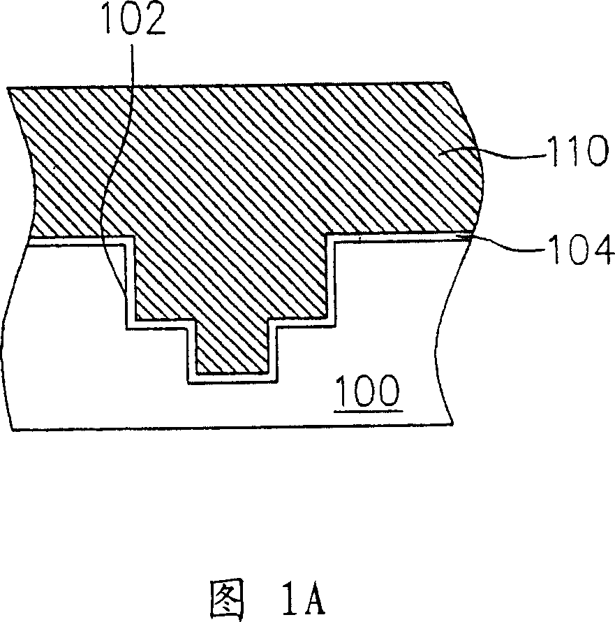
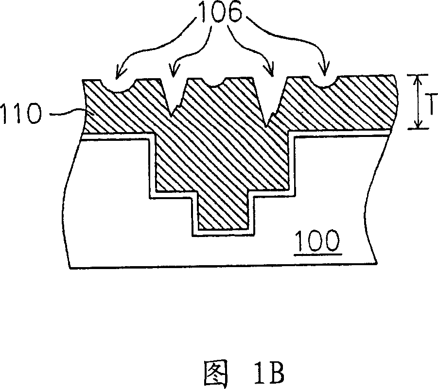
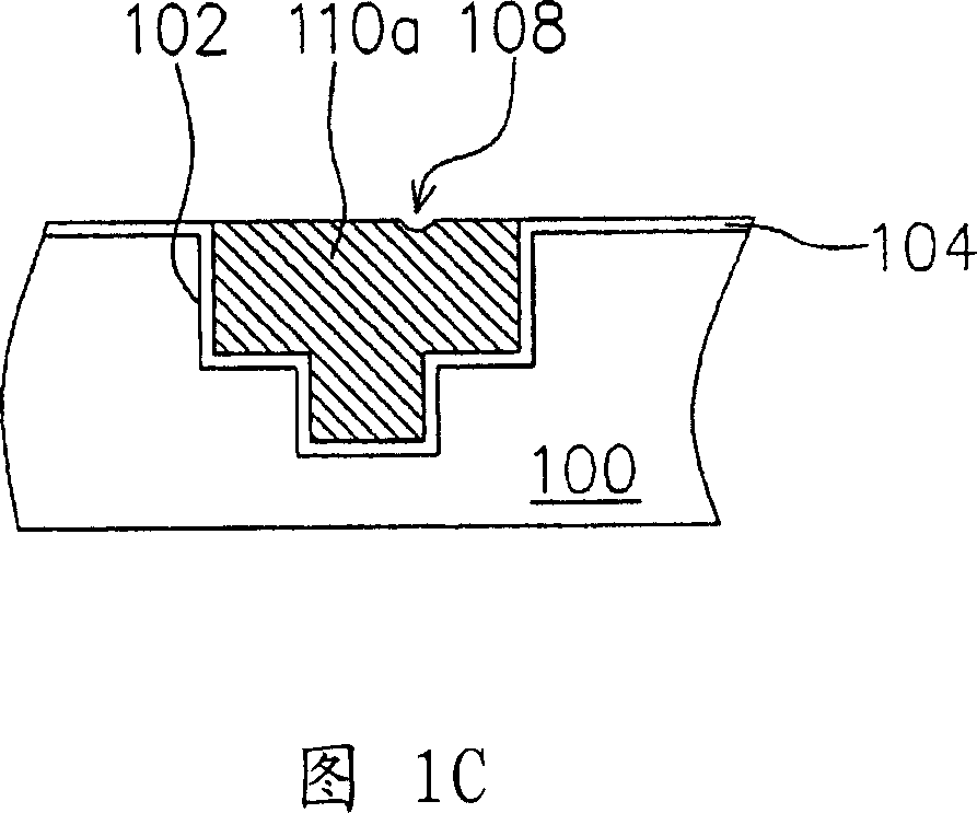
[0026] 1A to 1D are schematic cross-sectional views of a planarization process of a metal copper layer by using a copper chemical mechanical polishing method according to a first embodiment of the present invention.
[0027] Please refer to FIG. 1A first. In this embodiment, a layer of copper metal layer 110 is used as the layer to be polished, and this layer of copper metal layer 110 covers the substrate 100 having an opening 102 such as a double damascene opening and fills the opening. 102. Wherein, a barrier layer 104 may be formed between the substrate 100 and the copper metal layer 110 , and its material is, for example, selected from the group consisting of titanium nitride, titanium, tantalum, tantalum nitride and tungsten nitride. The substrate 100 may generally include a wafer, various semiconductor elements on the wafer, and a dielectric layer covering the semiconductor elements, etc., so it is not depicted in detail in the figure.
[0028] Afterwards, referring to ...
no. 2 example
[0032] 2 is a flow chart of the steps of the copper chemical mechanical polishing method according to the second embodiment of the present invention, which uses the copper metal layer covering the substrate with openings and filling the openings in the first embodiment as the layer to be polished.
[0033] Please refer to FIG. 2, in step 200, a first polishing pad is provided, and the type and material of the polishing pad can be changed as required. Then, in step 210, a first-stage polishing is performed on the first polishing pad to remove part of the thickness of the copper metal layer, and after this step, the thickness of the copper metal layer remaining on the surface of the substrate is, for example, between 500˜4000 angstroms or select an appropriate residual thickness according to the actual thickness of the copper metal layer and rules of thumb.
[0034] Then, in step 220, a second polishing pad is provided, which can be of the same or different type and material wit...
no. 3 example
[0037] 3 is a flow chart of the steps of the copper chemical mechanical polishing method according to the third embodiment of the present invention, which uses the copper metal layer covering the substrate with openings and filling the openings in the first embodiment as the layer to be polished.
[0038] Please refer to FIG. 3 , in step 300, the first-stage grinding is performed at a first grinding rate to remove part of the thickness of the copper metal layer, and after this step, the thickness of the copper metal layer remaining on the substrate surface is, for example, at 500 ~4000 angstroms, or select an appropriate residual thickness according to the actual thickness of the copper metal layer and empirical rules.
[0039] Next, in step 310, a second-stage grinding is performed at a second grinding rate to completely remove the copper metal layer outside the opening, wherein the second-stage grinding can be selected to continue grinding to remove the barrier layer outside ...
PUM
| Property | Measurement | Unit |
|---|---|---|
| Thickness | aaaaa | aaaaa |
Abstract
Description
Claims
Application Information