Efficient composite anaerobic reactor for treating high-concentration organic waste water
An anaerobic reactor and organic wastewater technology, applied in anaerobic digestion treatment, aerobic and anaerobic process treatment, waste fuel, etc., can solve the problems of easy plugging of fillers, reduction of processing load, artificial fixation, etc., and reduce investment Effects of cost, increased total biomass, and simplified design
- Summary
- Abstract
- Description
- Claims
- Application Information
AI Technical Summary
Problems solved by technology
Method used
Image
Examples
specific Embodiment approach 1
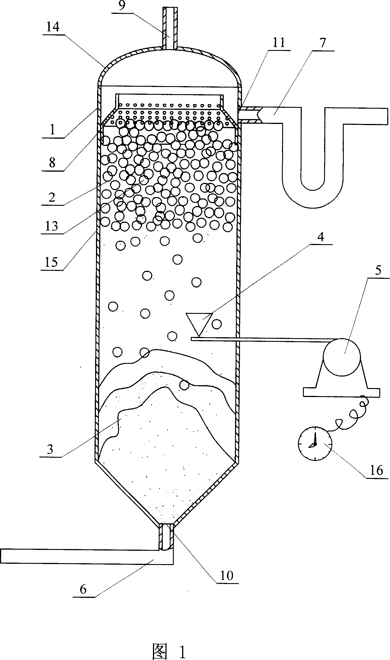
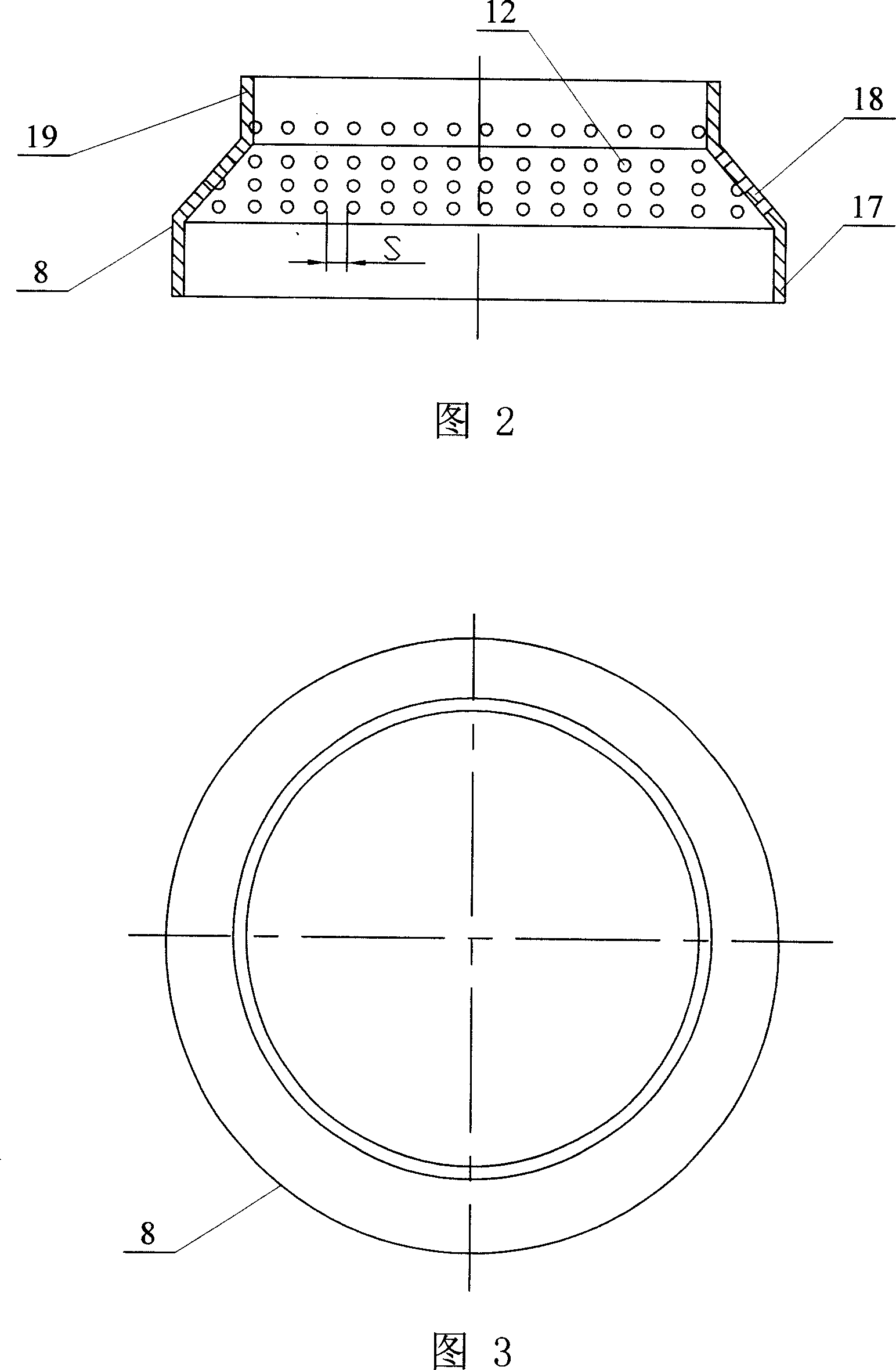
[0008] Specific embodiment 1: This embodiment is described in conjunction with Figures 1 to 3. This embodiment consists of a reaction vessel 1, a lightweight packed bed 2, an activated sludge bed 3, an aeration head 4, an air pump 5, an inlet pipe 6, and an outlet pipe 7 and water outlet weir 8; the top of the reaction vessel 1 is provided with a biogas outlet 9, the water inlet 10 at the bottom of the reaction vessel 1 communicates with the water inlet pipe 6, and the activated sludge bed 3, aeration head 4 and light The mass-packed bed 2 is arranged in the reaction vessel 1 sequentially in the order of pressing, middle and upper. The aeration head 4 is connected with the air pump 5 arranged outside the reaction vessel 1. One end of the outlet pipe 7 is connected to the upper side wall of the reaction vessel 1. The water outlet 11 on the top is connected, the water outlet weir 8 is arranged in the reaction vessel 1 and is installed close to the inner wall of the reaction vesse...
specific Embodiment approach 2
[0011] Specific embodiment two: this embodiment is described in conjunction with Fig. 1~Fig. 4, the distance S between two adjacent meshes 12 of the outlet weir 8 of this embodiment is 3~10cm, and the diameter of meshes 12 depends on lightweight packing Depending on the size of the light filler body 13, it is slightly smaller than the diameter D of the light filler body 13. While ensuring that the treated water flows out of the reaction vessel 1 smoothly, it can also prevent the light filler body 13 from flowing out of the reaction vessel 1 with the water flow. The weir 8 is made of plastic or stainless steel, which can be selected as required. Other components and connections are the same as those in the first embodiment.
specific Embodiment approach 3
[0012] Specific embodiment three: This embodiment is described in conjunction with Fig. 1~Fig. 4, and the difference between this embodiment and specific embodiment two is: the distance S between the adjacent two meshes 12 of the outlet weir 8 of this embodiment is 4cm. With such an arrangement, while ensuring that the treated water flows out of the reaction vessel 1 smoothly, it can also prevent the light packing body 13 from flowing out of the reaction vessel 1 with the water flow.
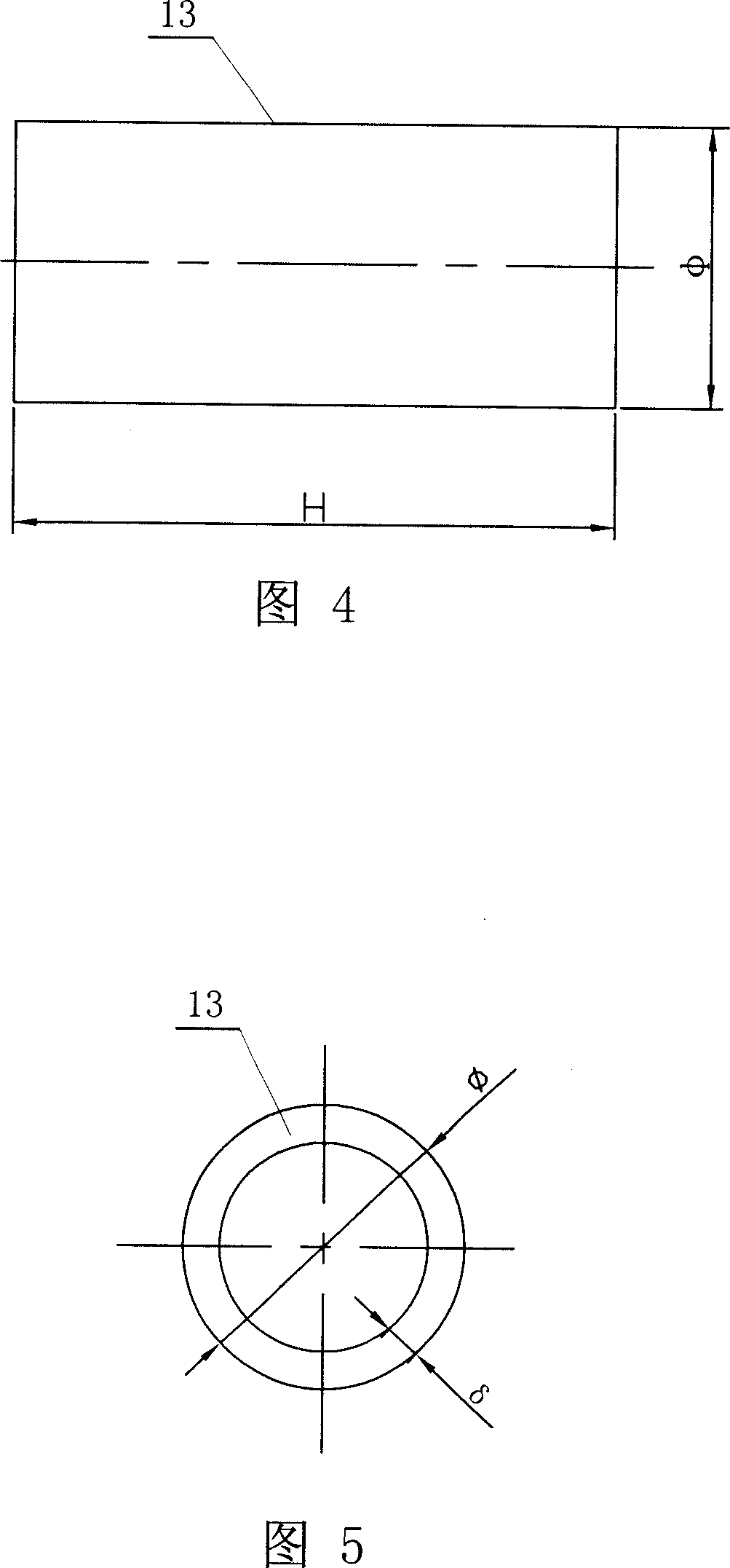
[0013] Specific Embodiment Four: This embodiment is described in conjunction with Fig. 1, Fig. 4 and Fig. 5, the shape of the lightweight filler body 13 of this embodiment is a circular tube shape, and the diameter D of the lightweight filler body 13 × height H × wall thickness δ 1-50mm×1-60mm×0.5mm respectively, the inner and outer surfaces of the lightweight filler body 13 can be designed in a zigzag shape to increase the area of the biofilm. The light filler body 13 is installed in the rea...
PUM
| Property | Measurement | Unit |
|---|---|---|
| density | aaaaa | aaaaa |
| diameter | aaaaa | aaaaa |
Abstract
Description
Claims
Application Information
 - R&D
- Intellectual Property
- Life Sciences
- Materials
- Tech Scout
- Unparalleled Data Quality
- Higher Quality Content
- 60% Fewer Hallucinations
Browse by: Latest US Patents, China's latest patents, Technical Efficacy Thesaurus, Application Domain, Technology Topic, Popular Technical Reports.
© 2025 PatSnap. All rights reserved.Legal|Privacy policy|Modern Slavery Act Transparency Statement|Sitemap|About US| Contact US: help@patsnap.com


