Biomass graded temperature-control slow pyrolysis process and its system

A biomass and rapid heating technology, applied in the fields of biofuels, petroleum industry, special forms of dry distillation, etc., can solve the problems of fast heating speed, reducing the gasification efficiency of gasification system, and the heating speed cannot be strictly controlled, so as to ensure the heating temperature. and heating speed, high comprehensive utilization efficiency, and the effect of improving comprehensive utilization

Active Publication Date: 2007-03-28
WUHAN KAIDI ENG TECH RES INST CO LTD
View PDF0 Cites 33 Cited by
  • Summary
  • Abstract
  • Description
  • Claims
  • Application Information

AI Technical Summary

Problems solved by technology

[0006] However, in the existing biomass pyrolysis pretreatment process, whether it is the autothermal method or the external heating method, the pyrolysis process of the above-mentioned stages is completed in only one pyrolysis reactor, and it is difficult to ensure that the entire pyrolyzer Uniformity of internal heating rate
Therefore, biomass raw materials in different locations may be in different stages of pyrolysis, which makes it difficult to meet proper pyrolysis conditions and cannot guarantee the quality of pyrolysis products
Especially for the pyrolysis process of self-heating mode, the following problems are more likely to occur: First, the local temperature in the combustion area is too high and the heating rate is too fast, which makes the temperature distribution in the entire pyrolysis reactor extremely uneven, and the heating rate cannot be strictly controlled. control, it is bound to make it difficult to meet the requirements of the operating temperature in the pyrolysis process, and then the pyrolysis products do not meet the requirements, which affects the subsequent gasification process; secondly, the self-heating method of partially burning biomass will make the CO in the pyrolysis gas 2 content significantly increased, thereby significantly reducing the gasification efficiency of the gasification system

Method used


Image

  • Biomass graded temperature-control slow pyrolysis process and its system

Examples


Embodiment Construction

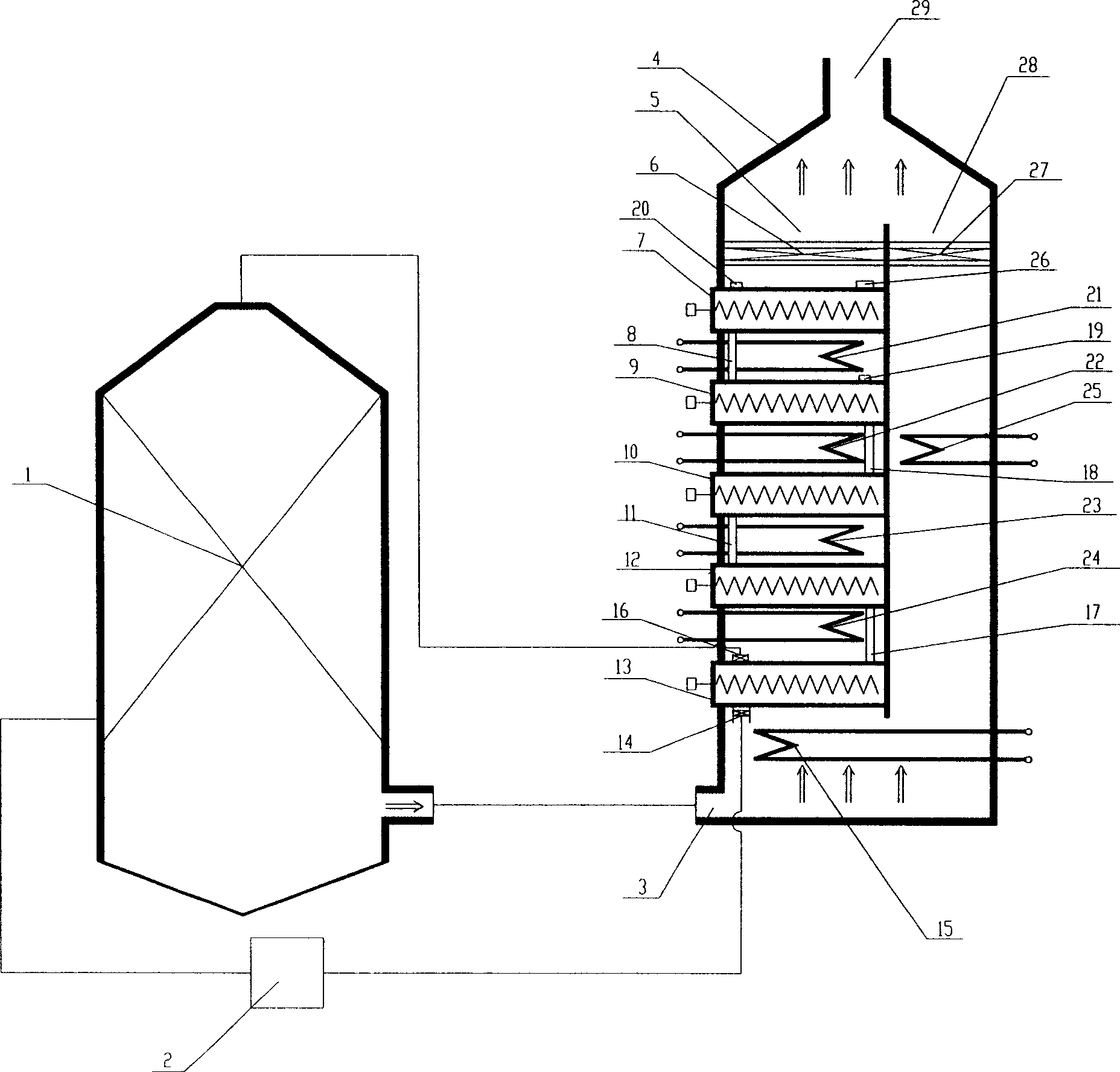
[0030] The biomass graded temperature controlled slow pyrolysis process and its system of the present invention will be further described in detail in conjunction with the accompanying drawings and specific examples:

[0031] The biomass graded temperature-controlled slow pyrolysis system shown in the figure has a vertically arranged system shell 4, and the bottom of the system shell 4 is designed with an external heat source inlet 3, which is directly gasified with biomass The high temperature synthesis gas output end of furnace 1 is connected. The top of the system shell 4 is designed with an outlet 29 of an external hot gas source, through which the high-temperature syngas cooled by heat exchange is sent to the follow-up processing equipment. A main heat exchanger 15 is installed at the bottom of the system shell 4 at the inlet 3 of the external hot gas source, and the main heat exchanger 15 first performs heat exchange and cooling of the incoming high-temperature synthesis...


PUM

PropertyMeasurementUnit
particle diameteraaaaaaaaaa
particle sizeaaaaaaaaaa

Abstract

The invention relates to biomass grading temperature controlling slow speed pyrolysis technology and its system. The technology includes the following steps: dividing the pyrolysis into many independent stages with temperature increasing; processing countercurrent flow for external heat source and biomass; heating the biomass grade by grade to make it pyrolyse; pre-drying and deep drying the material to make sure its water content is 5-10%; pre-charring and charring to gain charcoal, pyrolysis gas, little gas state biological crude oil; processing the secondary decompose for the crude oil at roasting stage to gain the pyrolysis product. The system is made up of external hot gas source and its bypass route, main heat exchanger, multiple-stage pyrolyzer, and multiple-stage heat exchanger. The invention has the advantages of wide material accommodation limit, easy adjustable pyrolysis process, easy controllable pyrolysis product, utilizing waste heat to increase gasification efficiency.

Description

technical field [0001] The invention belongs to the technical field of biomass energy and relates to the preparation of biomass pyrolysis products, in particular to a biomass graded temperature-controlled slow pyrolysis process and a system thereof. Background technique [0002] The development and utilization of biomass energy is a hot spot in the research and application of countries all over the world, and the biomass gasification technology aimed at producing various syngas has also been widely used. According to the characteristics of the biomass gasification process, it can be seen that the characteristics of the gasification raw materials and the particle size of the gasification raw materials will directly affect the operating load of the gasifier, the yield of syngas and tar, and the efficiency of raw material gasification. Various indicators. Usually, when different raw materials are reacted in different gasifiers, the requirements for their particle size are also...

Claims


Application Information

Patent Timeline
Patent Type & Authority Applications(China)
IPC IPC(8): C10B53/02
CPCY02E50/14Y02E50/10Y02P20/129
Inventor 吕锋杰张泽林冲金沙杨李宏宋侃杨占春张超
Owner WUHAN KAIDI ENG TECH RES INST CO LTD
Why Eureka
Try Eureka