Digital low power consumption high-precision high voltage generator

A high-voltage generator, low-power technology, used in X-ray equipment, electrical components, etc., can solve the problems of high price, high power, and few high-voltage generators, and achieve improved stability, high reliability, and light weight. Effect

Inactive Publication Date: 2007-03-28
CHENGDU UNIVERSITY OF TECHNOLOGY
View PDF0 Cites 12 Cited by
  • Summary
  • Abstract
  • Description
  • Claims
  • Application Information

AI Technical Summary

Problems solved by technology

[0003] At present, the high-voltage generators for medical X-ray tubes produced at home and abroad have large power, large volume, and high price, and are not suitable as power supplies for low-energy X-ray tubes that work continuously.
Existing low-energy high-voltage generators mostly use reverse transformers and voltage doubler rectifiers to generate high voltages. The circuits are relatively complex, and the voltage stabilization circuits are relatively simple, but it is difficult to meet the stability requirements of analytical instruments.
And many voltage stabilizing circuits mostly use analog devices, and rarely use software to realize their functions

Method used


Image

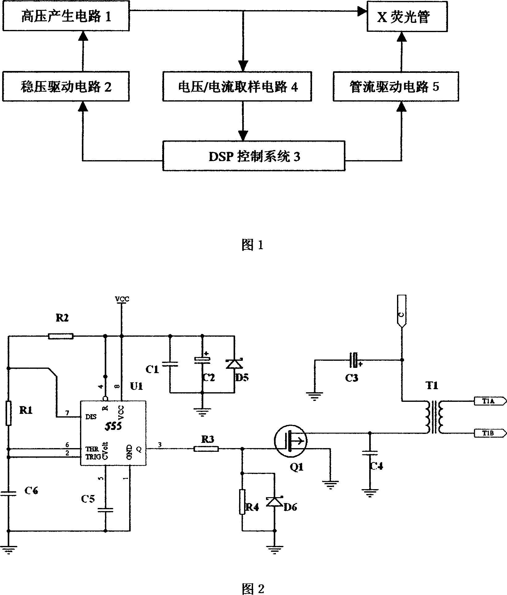
  • Digital low power consumption high-precision high voltage generator
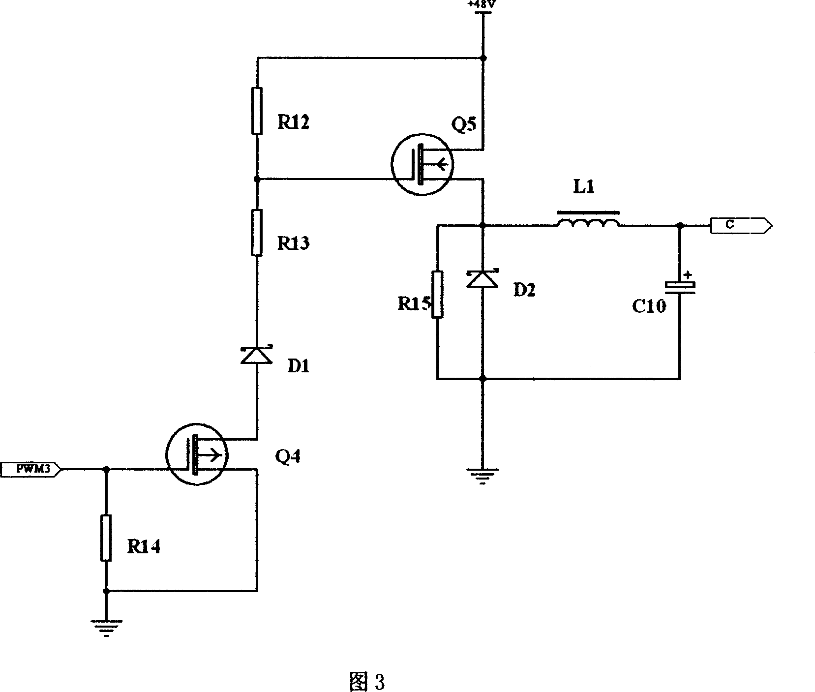
  • Digital low power consumption high-precision high voltage generator
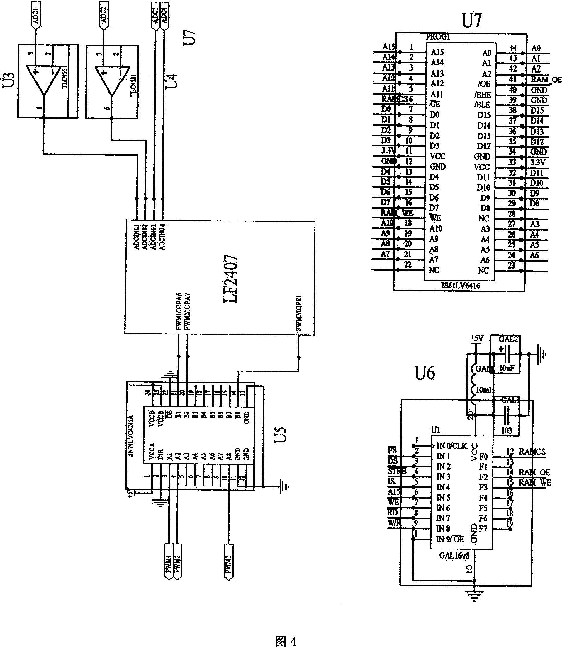
  • Digital low power consumption high-precision high voltage generator

Examples


Embodiment Construction

[0021] 1. High voltage generating circuit 1

[0022] The high-voltage generating circuit is shown in Figure 2, which is composed of a multivibrator, a field effect transistor (FET) Q1 and a flyback transformer (FBT) T1. The multivibrator composed of 555 timer U1 and R1, R2, C5, C6 outputs a rectangular pulse with a frequency of 18KHz (the duty cycle is about 50%) to drive Q1 to be turned on and off. When Q1 is turned on, the input voltage is applied to the primary winding of T1, and a voltage is induced in the secondary winding. When Q1 is cut off, the magnetic field energy stored in the primary winding will be released at the moment of disconnection and generate a high counter electromotive force, that is, the reverse voltage V1, and the voltage value can be obtained by the formula V 1 = - L di dt calculation. where L is the inductance of the core, is the rate of ...


PUM


Abstract

This invention relates to a technique based on DSP technology of digital low-power, high-precision and high voltage generator, including a high voltage generate circuit 1, steady voltage driving circuit regulators 2, DSP control system 3, current / voltage circuit sampling tube 4, and driven circuit 5. The high voltage circuit provides negative voltage for X-ray tubes, and produces current in the X-ray tubes. Current / voltage sampling circuit 4 samples the voltage / current which is provided to X-ray tube by high voltage circuit 1, and the sampling signal will be transmitted to the DSP control system 3. DSP control system samples the signals using the built-in 10 D synchronous analog-to-digital converter, analysis and processing. Converter Implementation of a high voltage output circuits have a negative high voltage X-ray tube and the current stability testing. Then PWM control signal wave will be output based on the test results, and put it on regulators driving circuit 2 and flow-driven circuit 5, and a closed-loop control circuit will be got, achieving the stability control of X-ray tube voltage and current.

Description

technical field [0001] The invention relates to a high-voltage power generating device, especially a digital low-power high-precision high-voltage generating device for a low-energy X-ray tube. Background technique [0002] In recent years, low-energy X-ray tubes have been widely used in various fields due to their many advantages, especially they are often selected as artificial excitation sources for X-ray fluorescence analysis systems. When the influence of other links in the system is ignored, the analysis results are affected by factors such as non-human adjustment changes and stability of X-ray exposure. The X-ray tube needs a high-voltage generator to supply power. The stability of the voltage and current of the high-voltage generator directly determines the stability of the X-ray exposure, and indirectly affects the reliability and measurement accuracy of the final analysis results. That is to say, the high-voltage generator The performance of the device determines ...

Claims


Application Information

Patent Timeline
Patent Type & Authority Applications(China)
IPC IPC(8): H05G1/10H05G1/32
Inventor 高嵩庹先国蔡顺燕穆克亮
Owner CHENGDU UNIVERSITY OF TECHNOLOGY
Why Eureka
Try Eureka