System and method for reducing surge

A turbocharger, exhaust manifold technology, applied in combustion engines, machines/engines, internal combustion piston engines, etc., can solve problems such as surge and deterioration

Inactive Publication Date: 2007-04-04
FORD GLOBAL TECH LLC
View PDF2 Cites 15 Cited by
  • Summary
  • Abstract
  • Description
  • Claims
  • Application Information

AI Technical Summary

Problems solved by technology

[0005] However, the inventors of the present application have found that this approach may yield degraded results under certain conditions and still result in surge

Method used


Image

  • System and method for reducing surge
  • System and method for reducing surge
  • System and method for reducing surge

Examples


Embodiment Construction

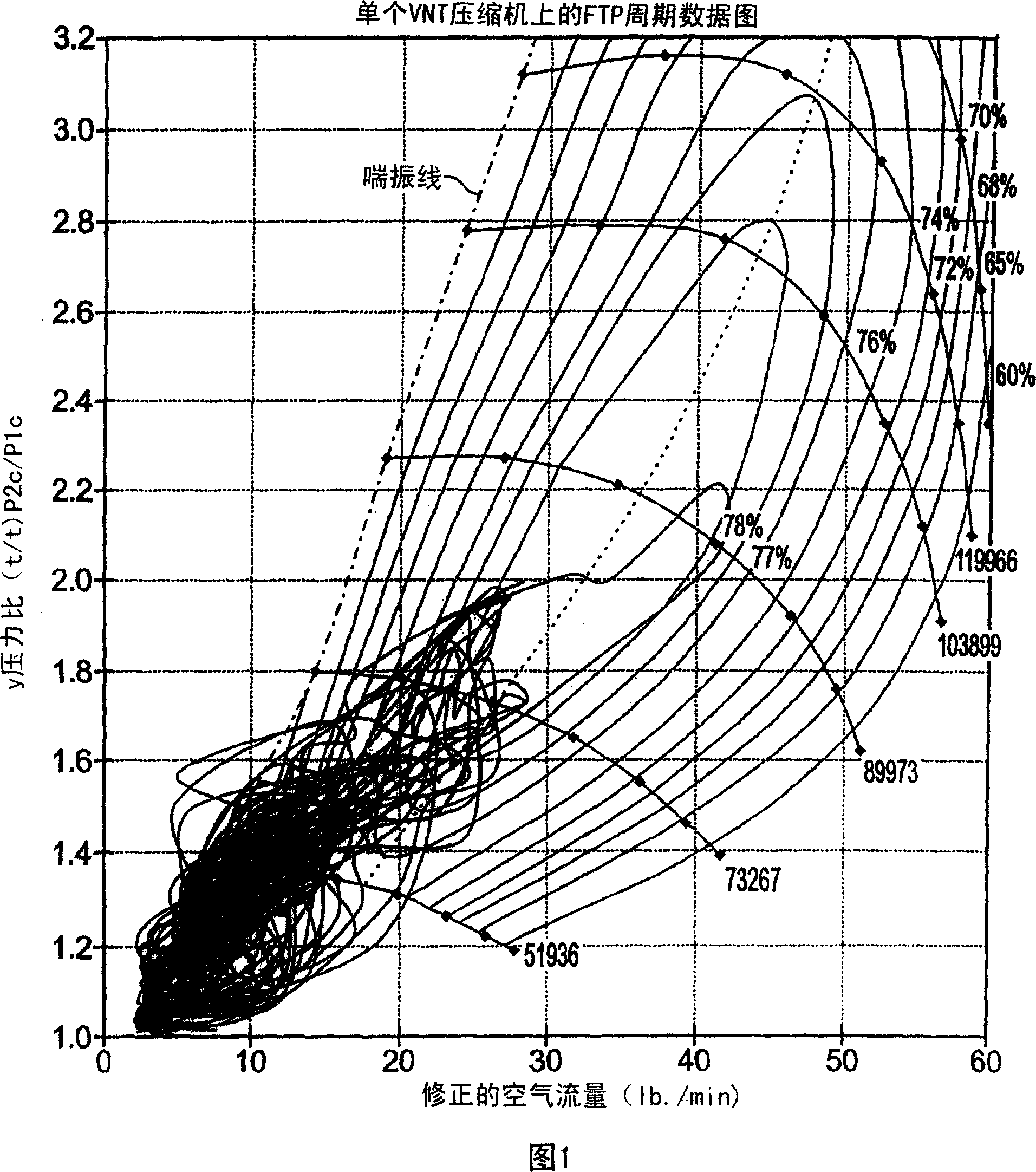
[0017] Figure 1 shows a Federal Test Procedure (FTP) cycle diagram on a single VNT compressor. As shown, the surge line is dashed. In Figure 1, during the FTP cycle, certain operating points with moderate EGR (including only light release of the accelerator) enter the surge line. Compressor surge can cause additional noise and can cause compressor damage.

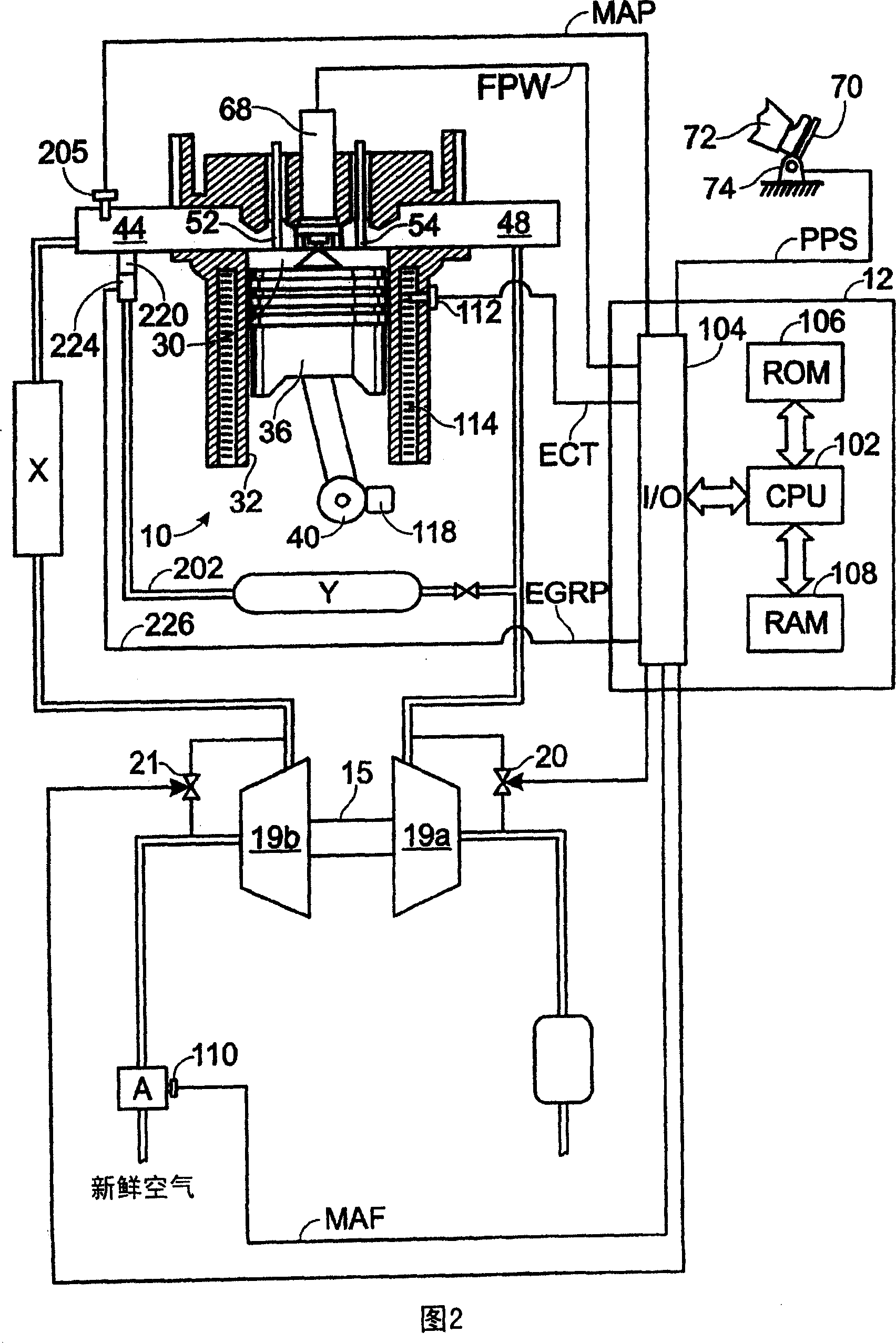
[0018] Shown in Figure 2 is an example of a turbocharged engine with an EGR system. Specifically, internal combustion engine 10 includes a plurality of cylinders, one of which is shown in FIG. 2 , which is controlled by electronic engine controller 12 . Engine 10 includes combustion chamber 30 and cylinder walls 32 with piston 36 positioned therein and connected to crankshaft 40 . Combustion chamber 30 communicates with intake manifold 44 and exhaust manifold 48 via respective intake valve 52 and exhaust valve 54 . As shown, intake manifold 44 also includes fuel injector 68 coupled thereto for delivering fuel proportion...


PUM


Abstract

A method of controlling an engine having an intake manifold and an exhaust manifold, wherein an exhaust gas recirculation path having a valve is provided between the intake and exhaust manifolds, and the engine has a turbocharger ; the method comprising increasing the opening of the exhaust gas recirculation valve when there is at least one condition of reduced engine output; and adjusting exhaust gas expansion through the turbocharger turbine to reduce expansion through the turbocharger. Reducing turbocharger expansion will reduce the power input to the compressor and slow down the compressor. At the same time, the pressure differential between the intake and exhaust manifolds increases due to the reduced pressure on the exhaust manifold side (because of the reduced expansion). Therefore, more airflow from the intake side can flow into the exhaust side for efficient exhaust to the intake manifold. As a result, the pressure at the outlet of the compressor is further reduced. Thus, such manipulation can reduce the likelihood of surge through the synergistic effect of the two actions.

Description

technical field [0001] The present invention relates generally to the control of diesel powered internal combustion engines and, more particularly, to systems and methods for eliminating surge surge in turbocharged diesel engines. Background technique [0002] The engine may use a turbocharger to increase the torque / power output density of the engine. In one example, a turbocharger may include a compressor and a turbine connected by a common shaft, where the turbine is connected to the exhaust manifold side and the compressor is connected to the intake manifold side. In this way, the exhaust-driven turbine powers the compressor to enhance airflow into the engine. [0003] Under certain conditions, turbocharged diesel engines can develop a phenomenon known as "surge". For example, during a driver's emergency release of the accelerator, the engine slows down and the turbocharger continues to spin for a while before gradually slowing down. This delay is at least partially du...

Claims


Application Information

Patent Timeline
Patent Type & Authority Applications(China)
IPC IPC(8): F02B37/12
CPCF02B37/16F02B37/18F02B37/12F02B37/004Y02T10/144F02B37/013F02B37/24Y02T10/12
Inventor 哈罗德·孙理查德·贝克约翰·H·范德史莱斯杰弗里·B·施内亚威廉·洛纳
Owner FORD GLOBAL TECH LLC
Why Eureka
Try Eureka