
Temp. data collecting and controlling system of engineering mechanical hydraulic motor radiating system

A technology of hydraulic motor and heat dissipation system, which is applied in the direction of electric speed/acceleration control, electric temperature control, speed/acceleration control, etc., which can solve problems such as system overheating, waste of fuel, and large machine wear, and achieve reduction Noise of the whole machine, improving utilization rate, and solving the effect of large wear and tear

Inactive Publication Date: 2007-04-18
GUANGXI LIUGONG MASCH CO LTD
View PDF0 Cites 20 Cited by
  • Summary
  • Abstract
  • Description
  • Claims
  • Application Information

AI Technical Summary

Problems solved by technology

[0003] 1. The fan speed is always consistent with the engine speed, and the fan speed cannot be adjusted according to the environmental requirements
For example: when the machine is used in a hot environment, the fan speed cannot be increased to enhance the heat dissipation capacity of the cooling system, resulting in overheating of the system, causing large wear of the machine, and easy aging of the seals; when used in a colder environment, it is also impossible Reduce the fan speed to reduce the heat dissipation capacity of the heat dissipation system, resulting in low system temperature, high oil viscosity, low machine efficiency and other problems
[0004] 2. The position of the fan is fixed (it must be connected with the output shaft of the engine fan), and the position of the cooling system is also relatively fixed, resulting in inflexible layout of the overall design of the machine
[0005] 3. Low utilization rate of engine power, waste of fuel

Method used


Image

  • Temp. data collecting and controlling system of engineering mechanical hydraulic motor radiating system
  • Temp. data collecting and controlling system of engineering mechanical hydraulic motor radiating system

Examples


Embodiment Construction

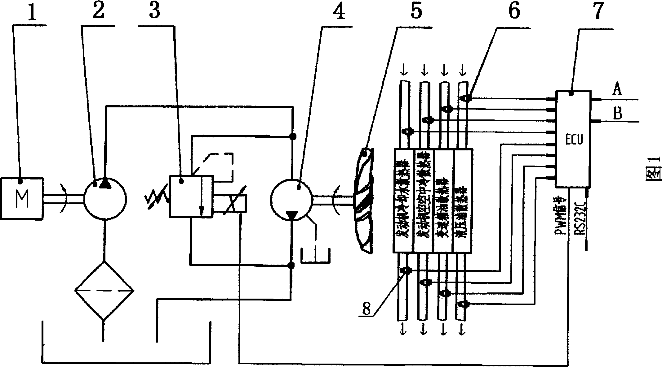
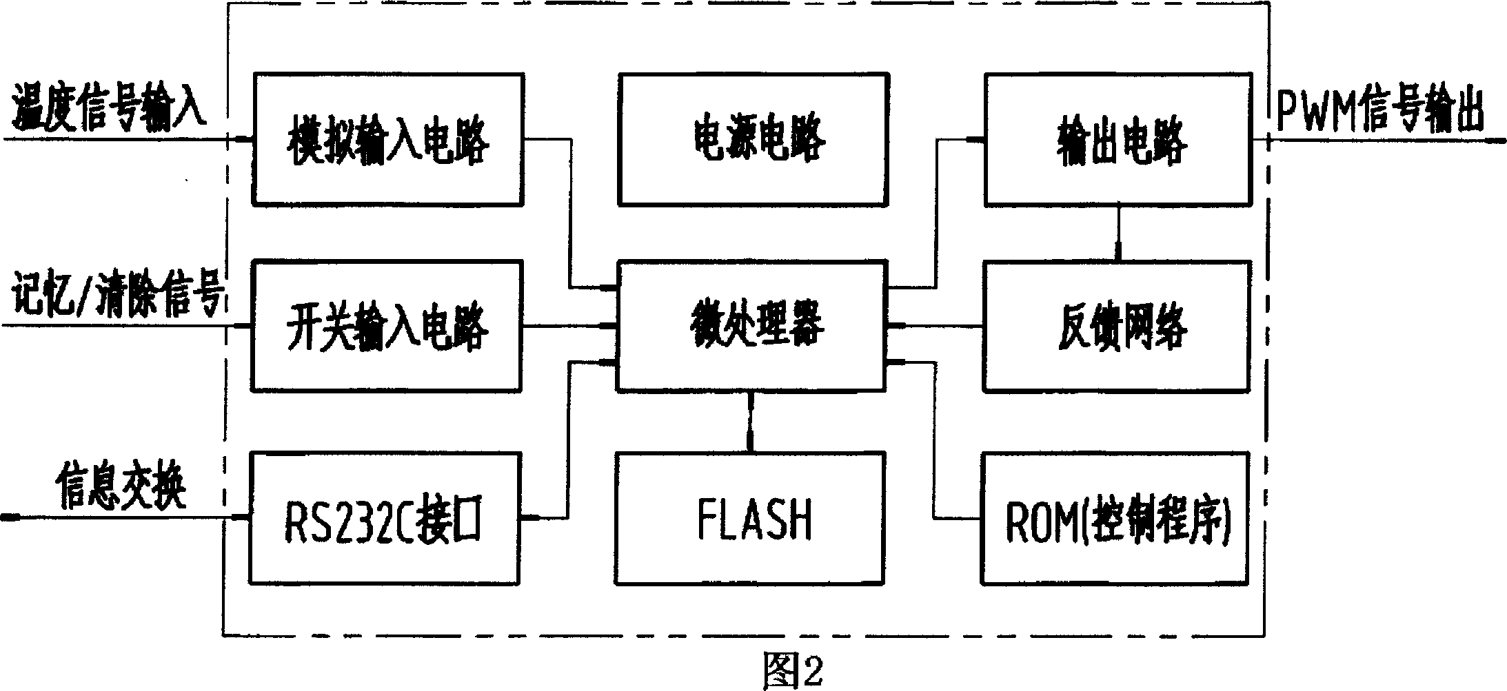
[0013] In the present invention, the quantitative motor 4 drives the fan 5, and a temperature sensor 8 is installed at the outlet of the heat dissipation assembly. The signal transmitted by the temperature sensor 8 controls the proportional electromagnetic pressure reducing valve 3 to realize the adjustment of the fan 5, and is installed at the entrance of the heat dissipation assembly. The temperature sensor 6 collects the inlet and outlet temperatures of the heat dissipation components at the same time; it has an electronic control unit (ECU) to control the collected signals, generate corresponding driving current, and drive the proportional electromagnetic pressure reducing valve.

[0014] The heat dissipation assembly refers to the engine cooling water radiator, and the electronic control unit (ECU) has a control circuit that controls the change data of the inlet temperature of the engine cooling water radiator between its specified lower limit value and upper limit value, ...


PUM


Abstract

The invention relates to engineering machine hydraulic motor heat elimination system temperature data acquisition and control system. Its features are that using constant displacement motor to drive fan; setting temperature sensor at the outlet of the heat elimination assembly; using its transmitted signal to control proportion electromagnetism pressure reducing valve and adjust the fan; setting the temperature sensor at its inlet to process synchronous acquisition for the outlet and inlet temperature; using electronic control unit to control the acquired signal to generate corresponding drive current and drive proportion electromagnetism pressure reducing valve. Its advantages are that it can control machine working temperature range by controlling fan rotate speed, record each heat radiator inlet and outlet temperature and proportion electromagnet drive current data, estimate the match and performance of the radiator according to the data; it has high utilization factor for engine power; and it can save fuel.

Description

technical field [0001] The invention relates to a temperature data acquisition and control system of a hydraulic motor cooling system of an engineering machinery. Background technique [0002] At present, the fans of domestic construction machinery cooling systems are generally directly driven by the fan output shaft of the engine. There are two main disadvantages in this way: [0003] 1. The fan speed is always consistent with the engine speed, and the fan speed cannot be adjusted according to the environmental requirements. For example: when the machine is used in a hot environment, the fan speed cannot be increased to enhance the heat dissipation capacity of the cooling system, resulting in overheating of the system, causing large wear of the machine, and easy aging of the seals; when used in a colder environment, it is also impossible Reduce the fan speed to reduce the heat dissipation capacity of the heat dissipation system, resulting in low system temperature, high o...

Claims


Application Information

Patent Timeline
IPC IPC(8): G05D13/66G05D13/62G05D23/19
Inventor 朱斌强李开亮陈前锋
Owner GUANGXI LIUGONG MASCH CO LTD
Learn More