Pipe cutter

A technology of pipe cutting machine and cutting mechanism, which is applied in the direction of pipe shearing device, shearing device, metal processing machinery parts, etc., can solve the problems of high labor intensity, high processing cost, low production efficiency, etc., and achieve high degree of automation and labor efficiency. The effect of low strength and high production efficiency

Inactive Publication Date: 2007-04-25
陈永真
View PDF0 Cites 46 Cited by
  • Summary
  • Abstract
  • Description
  • Claims
  • Application Information

AI Technical Summary

Problems solved by technology

Grinding wheel cutting machine grinding, bow sawing machine and band sawing machine sawing, and manual cutter ring cutting all have the following defects: 1. The loading and unloading adopts manual adjustment screw rod to compress and loosen the pipe fittings (ie pipe workpieces), and its speed is slow; 2. The length of the ruler is manually controlled, and the size is inaccurate; 3. During the processing of pipe fittings, the pipe fittings are still, and the verticality between the cutting end surface and the pipe axis is low; 4. The processing process, especially batch processing, uses manual clamping, loosening, feeding, and positioning. ruler, etc., which is labor-intensive and low in production efficiency
Although ordinary lathes have overcome the third shortcoming above, they still have the following defects: high labor intensity, low production efficiency, and high processing costs
[0003] Although the Chinese patent application documents disclose some pipe cutting machines, some are limited to large-diameter pipelines for on-site construction and maintenance, others focus on PVS pipe chamfering, and others are limited to certain devices of the pipe cutting machine such as cutting Feed device improvement, etc.
So far, no pipe cutting machine has been found with full functions, high degree of automation and can be widely used in technical fields such as machinery manufacturing and batch processing of pipe products.

Method used


Image

  • Pipe cutter
  • Pipe cutter
  • Pipe cutter

Examples


Embodiment Construction

[0025] The present invention will be described in further detail below in conjunction with the accompanying drawings and specific embodiments.

[0026] As shown in Figure 1 and Figure 14 (all the descriptions below refer to these two figures).

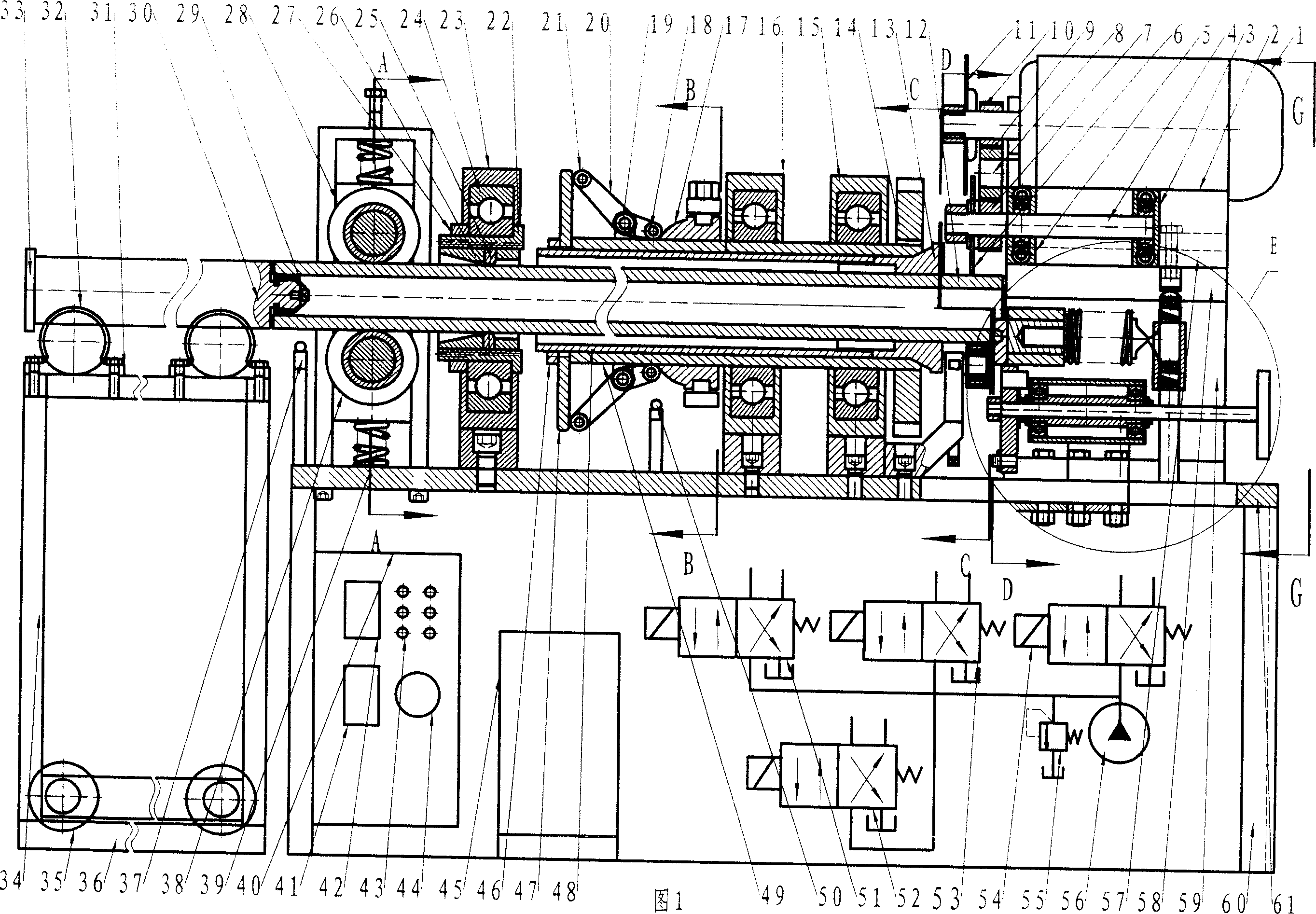
[0027] The pipe cutting machine includes a frame 60, a worktable 61, an air pressure or hydraulic device, a connecting pipe valve, and a cutting motor 1 axially installed at one end of the workbench 61. The valves of the pneumatic or hydraulic device include control valves 81 , 90 , 109 , 120 , overflow valve 55 , cooling valve 110 and the like. It also includes power and electrical control circuits. The electric control box 40 is arranged on the frame 60, and the main power switch 42, the control button 43, the counter 41, the buzzer 44, etc. are arranged on the positive side of the electric control box 40.

[0028] It also includes a cutting mechanism driven by a cutting motor 1 . The worktable 61 and the frame 60 are provided wit...


PUM


Abstract

The invention relates to a pipe cutter, which comprises: frame (60), work table (61), aerated or hydraulic device, connecting tube valve, cutting motor (1) axially mounted at one end of work table (61), and the cutter driven by said motor (1). Wherein, the work table (61) and frame (60) are mounted with a device for moving cutting motor (1) and cutter up and down, and a device for rotating the pipe (12) around its axle; the end of work table (61) far from the motor (1) has automatic pipe feeder; the work table (61) between cutter and pipe feeder is mounted with pipe guide support and pipe automatic clamper; one side of motor (1) has pipe (12) automatic sizing device under. The invention has high vertical degree between cutting surface and pipe axle, with high efficiency and low cost.

Description

technical field [0001] The invention relates to a mechanical processing equipment, in particular to a pipe cutting machine. Background technique [0002] The pipe cutting of the prior art generally adopts an emery wheel cutting machine to grind off, a bow sawing machine and a band sawing machine to saw off, a manual cutter ring cut and a common lathe to cut off, etc. Grinding wheel cutting machine grinding, bow sawing machine and band sawing machine sawing, and manual cutter ring cutting all have the following defects: 1. The loading and unloading adopts manual adjustment screw rod to compress and loosen the pipe fittings (ie pipe workpieces), and its speed is slow; 2. The length of the ruler is manually controlled, and the size is inaccurate; 3. During the processing of pipe fittings, the pipe fittings are still, and the verticality between the cutting end surface and the pipe axis is low; 4. The processing process, especially batch processing, uses manual clamping, looseni...

Claims


Application Information

Patent Timeline
Patent Type & Authority Applications(China)
IPC IPC(8): B23D21/00B21D43/08B23D33/02B23D33/12B23P23/02B23B5/16B23Q11/10
Inventor 陈永真
Owner 陈永真
Why Eureka
Try Eureka