Installation of cooling and melting ice and snow for road surface and bridge road by using underground natural energy resource

A technology of natural energy and road and bridge decks, applied in heating devices, geothermal power generation, roads, etc., can solve hidden dangers of building safety, expensive machinery, waste of resources, etc., and achieve low operation and maintenance costs and long equipment life cycle The effect of long and prolonging the service life

Inactive Publication Date: 2007-05-09
HARBIN INST OF TECH
0 Cites 12 Cited by

AI-Extracted Technical Summary

Problems solved by technology

[0003] The present invention solves the existing problems of the existing road and bridge deck deicing methods: 1. Make the melted salt water penetrate into the reinforced concrete, causing severe corrosion to the structure, speeding up the damage to the building, and bringing safety problems to the building. 2. Large investment and high energy consumption; 3. This snow removal method not only causes certain damage to the road...

Method used

[0011] The applicant is 50m long in Beijing, and the road (bridge) surface of 6m has been simulated and calculated. Among them, the shallow heat exchanger 7 buried in the road (bridge) surface is a high-density polyethylene pipe, the inner diameter of the pipe is d1=21.25mm, the outer diameter is d2=26.75mm, the length is 5.5m, and the distance between the pipes is 200mm. The buri...

Abstract

The present invention relates to a road bridge surface cooling and snow-melting equipment by utilizing underground natural energy source. It is characterized by that said equipment includes a first circulation pump, its two ends are respectively connected with condenser and one end of first valve, two ends of shallow layer heat-exchanger are respectively connected with one end of first valve, one end of second valve and one end of fourth valve, two ends of said condenser are respectively connected with one end of first valve and one end of second valve, two ends of evaporator are respectively connected with one end of fifth valve and one end of sixth valve, two ends of deep layer heat-exchanger are respectively connected with one end of seventh valve, one end of sixth valve and one end of fourth valve and two ends of second circulation pump are respectively connected with one end of seventh valve, one end of fifth valve and one end of third valve.

Application Domain

Technology Topic

RebarSurface cooling +8

Image

  • Installation of cooling and melting ice and snow for road surface and bridge road by using underground natural energy resource

Examples

  • Experimental program(2)

Example Embodiment

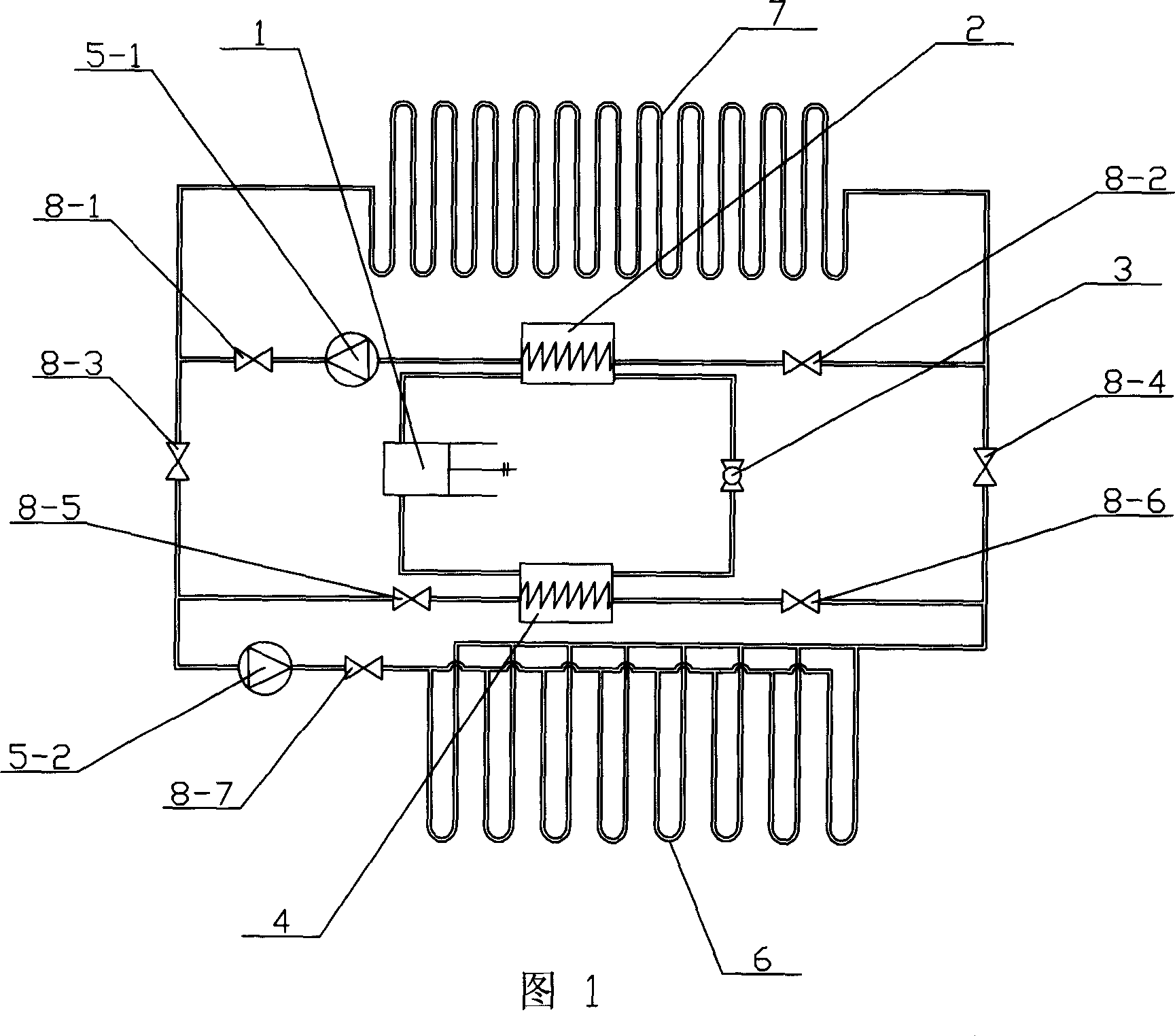
[0007] Specific implementation manner 1: This implementation manner is described with reference to FIG. 1. This embodiment consists of compressor 1, condenser 2, expansion valve 3, evaporator 4, circulating pump 5, deep heat exchanger 6, shallow heat exchanger 7, first control valve 8-1, and second control valve 8. -2. The third control valve 8-3, the fourth control valve 8-4, the fifth control valve 8-5, the sixth control valve 8-6 and the seventh control valve 8-7 are composed. The input end of the first circulating pump 5-1 is connected to the first output end of the condenser 2 tube pass, the output end of the first circulating pump 5-1 is connected to the input end of the first control valve 8-1, and the first control The output end of the valve 8-1 is respectively connected to the input end of the shallow heat exchanger 7 and one end of the third control valve 8-3, and the output end of the shallow heat exchanger 7 is connected to the second control valve 8-2 and the fourth control valve 8-2. One end of the control valve 8-4 is connected, the other end of the second control valve 8-2 is connected to the first input end of the condenser 2 tube pass, and the other end of the fourth control valve 8-4 is connected to the sixth control valve 8-6 One end of the evaporator is connected to the output end of the deep heat exchanger 6, the other end of the sixth control valve 8-6 is connected to the first input end of the evaporator 4 tube pass, and the first output end of the evaporator 4 tube pass is connected to the fifth control One end of the valve 8-5 is connected, and the other end of the fifth control valve 8-5 is respectively connected to the other end of the third control valve 8-3 and the input end of the second circulating pump 5-2, and the second circulating pump 5-2 The output end of the seventh control valve 8-7 is connected to one end, and the other end of the seventh control valve 8-7 is connected to the input end of the deep heat exchanger 6. Ethylene glycol solution is used in the pipeline.
[0008] Both the deep heat exchanger 6 and the shallow heat exchanger 7 use high-density polyethylene pipes or steel pipes

Example Embodiment

[0009] Specific implementation manner 2: This implementation manner is described with reference to FIG. 1. The input end of the compressor 1 of this embodiment is connected to the second output end of the shell side of the evaporator 4, the output end of the compressor 1 is connected to the second input end of the shell side of the condenser 2, and one end of the expansion valve 3 is connected to the evaporator. The second input end of the shell side 4 is connected, and the other end of the expansion valve 3 is connected to the second output end of the shell side of the condenser 2.
[0010] Both the deep layer heat exchanger 6 and the shallow layer heat exchanger 7 use high-density polyethylene pipes or steel pipes, the road (bridge) shallow layer heat exchanger 7 pipe spacing is controlled between 150mm and 300mm, and the shallow layer heat exchanger 7 The embedment depth is 50mm~80mm from the ground (bridge) surface, which should be determined according to the load on the road (bridge) surface, the temperature of the pipe and the heating fluid in the buried pipe. The underground energy pipe is calculated from the load on the bridge (road) surface and the heat exchange per unit drilling depth is 50-100W/m. The drilling depth is controlled at 40-100m, not too deep, otherwise the cost is high.
[0011] The applicant conducted a simulation calculation on a road (bridge) surface with a length of 50m and a width of 6m in an area of ​​Beijing. Among them, the shallow heat exchanger 7 embedded in the road (bridge) plane is a high-density polyethylene pipe, and the inner diameter of the pipe is d 1 =21.25mm, outer diameter d 2 = 26.75mm, the length is 5.5m, the distance between the tubes is 200mm, and the buried depth of the shallow heat exchanger 7 is 80mm. The deep-layer heat exchanger 6 is buried longitudinally with a buried depth of 80m. The deep-layer heat exchanger 6 uses a high-density polyethylene tube with an outer diameter of 33.5mm and an inner diameter of 27mm. Choose a heat pump unit with a heating capacity of about 140KW, and the effect of removing ice and snow on the bridge deck heating is good.
[0012] The working principle of this device:
[0013] The operating mode of this device during winter snow melting:
[0014] Close the third control valve 8-3, the fourth control valve 8-4, the first control valve 8-1, the second control valve 8-2, the fifth control valve 8-5, and the sixth control valve 8-6. The seventh control valve 8-7 is opened, and the deep heat exchanger 6 sends the heat energy obtained by the underground temperature of 10℃ (Shenyang area) to the heat pump circulation system through the sixth control valve 8-6, and then the first circulation pump 5- 1 Through the first control valve 8-1, the heated glycol solution is input to the shallow heat exchanger 7 buried under the road (bridge) surface, and the shallow heat exchanger 7 dissipates heat to the road surface (the ground temperature is above 0℃) ), to melt the snow and ice on roads and bridges.
[0015] The operation mode of the cooling device in summer:
[0016] Close the first control valve 8-1, the second control valve 8-2, the fifth control valve 8-5, and the sixth control valve 8-6, the third control valve 8-3, the fourth control valve 8-4, and the The seventh control valve 8-7 is opened, and the low temperature solution obtained from the deep heat exchanger 6 enters the shallow heat exchanger 7 through the fourth control valve 8-4. The shallow heat exchanger 7 absorbs the high temperature of about 40℃ on the ground. From the other end of the shallow heat exchanger 7, the absorbing glycol solution returns to the deep heat exchanger 6 via the second circulating pump 5-2 through the other end of the third control valve 8-3 to circulate, reaching the summer road, The purpose of cooling the bridge deck or ground.

PUM

PropertyMeasurementUnit
The inside diameter of21.25mm
Outer diameter26.75mm
Length5.5m
tensileMPa
Particle sizePa
strength10

Description & Claims & Application Information

We can also present the details of the Description, Claims and Application information to help users get a comprehensive understanding of the technical details of the patent, such as background art, summary of invention, brief description of drawings, description of embodiments, and other original content. On the other hand, users can also determine the specific scope of protection of the technology through the list of claims; as well as understand the changes in the life cycle of the technology with the presentation of the patent timeline. Login to view more.

Similar technology patents

Universal mechanism

Owner:GUIZHOU AEROSPACE ELECTRONICS TECH

Surgical laparoscope device with view angle capable of being controlled by surgeon

PendingCN112754844AReduce applicationsReduce the number of pipesOperating tablesLaproscopesOperative laparoscopyInvasive surgery
Owner:黄明

Intelligent antenna network calibration method

InactiveCN112019280AReduce applicationsReduce calibration costsTransmitters monitoringReceivers monitoringRadio frequencyTransceiver
Owner:安徽蓝煜电子科技有限公司

Laying method for lining of reduction furnace

Owner:岷山环能高科股份公司

Classification and recommendation of technical efficacy words

  • Reduce applications
  • Reduce corrosion

Tankless water heater

InactiveUS20080107410A1Reduce corrosionImmersion heating arrangementsBeverage vesselsMagnetEngineering
Owner:DOLPHIN IND

High acid value hydrocarbon oil delayed coking method

ActiveCN1580193AReduce corrosionExtend the coking start-up periodThermal non-catalytic crackingProduct gasComing out
Owner:CHINA PETROLEUM & CHEM CORP +1

Metal corrosion inhibitor

Owner:CHINA PETROCHEMICAL CORP +1
Why Eureka
Try Eureka