Transpirationcooled wind driven generator stator

A technology of evaporative cooling and machine stator, which is applied to the static parts of the magnetic circuit, the shape/style/structure of the magnetic circuit, etc., can solve the problems of water difficulty, hot spots of heating components, and reduce the service life of winding insulation, etc., and achieve physical and chemical properties Good, no local hot spots, and the effect of suppressing corona discharge

Active Publication Date: 2007-05-09
INST OF ELECTRICAL ENG CHINESE ACAD OF SCI
View PDF0 Cites 35 Cited by
  • Summary
  • Abstract
  • Description
  • Claims
  • Application Information

AI Technical Summary

Problems solved by technology

The disadvantages are: due to the air medium and the structural arrangement of the cooling channel, the temperature distribution of the stator and rotor cores and windings of the air-cooled wind turbine is uneven, and there are hot spots in the heating parts, which may damage the winding insulation and reduce the service life of the winding insulation
The disadvantage is: the commonly used cooling structure of water-cooled wind turbines is to add a "water jacket" to the motor stator casing to achieve cooling purposes
However, this cooling structure cannot directly cool the heat-generating components like a large water-cooled generator. Therefore, the temperature distribution of the stator and rotor cores and windings of the generator is not uniform, and the ideal cooling effect cannot be completely achieved fundamentally.
Moreover, the most important thing is that most of the wind turbines are installed in the wild, and it is difficult to use water, which brings great difficulties to the operation of the generators.
[0005] With the development of wind power generation technology, the stand-alone capacity of wind power generators continues to increase, especially for megawatt wind power generators, which are required to have relatively small volume, high power density, light weight, safe and reliable operation, etc. The above two cooling methods and structures are difficult to meet these requirements

Method used


Image

  • Transpirationcooled wind driven generator stator
  • Transpirationcooled wind driven generator stator
  • Transpirationcooled wind driven generator stator

Examples


Embodiment Construction

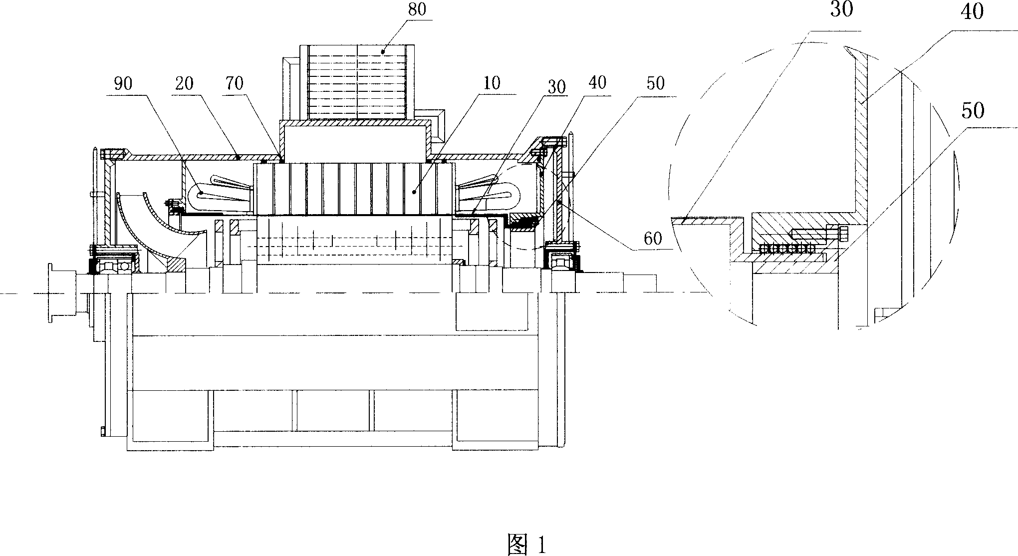
[0027] The specific implementation manner of the stator structure of the evaporative cooling wind power generator is described in conjunction with the accompanying drawings.

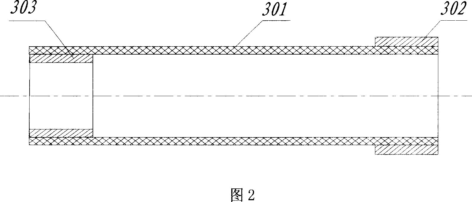
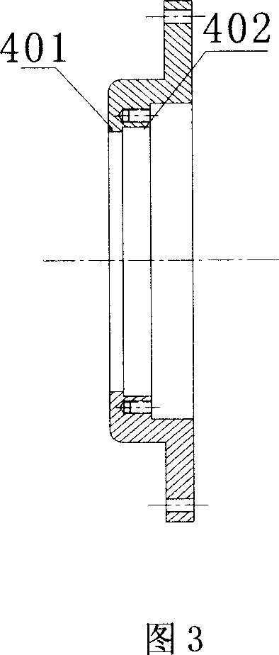
[0028] The evaporative cooling wind turbine stator includes the wind turbine stator and the evaporative cooling circuit. As shown in FIG. 1 , the main components constituting the stator of the wind power generator include a stator core segment 10 , a stator slot, a stator winding coil and a stator end winding 90 . The stator casing 20, the non-magnetic stainless steel isolation sleeve 30, the end sealing end cap 40 and the pressure stop ring 50 form the stator enclosed space, and the main components of the stator are installed in the stator enclosed space: the stator core segment 10 is installed in the stator casing 20 Inside, the non-magnetic stainless steel isolation sleeve 30 is installed at the inner circle of the stator core segment 10 , and the end sealing end caps 40 are installed at both ends of ...


PUM


Abstract

The tightly closed space of the stator consists of the stator chassis, the non-magnetic stainless steel isolated sleeve, the tightly closed end cap and the pressuring ring. The cooling loop consists of the liquid-lead groove between the stator core sections, the stator winding/ stator end winding, the stator vaporizing space and the air condenser (AC). Via the gas entering tube and the liquid returning tube, AC connects to the stator chassis to form a main cooling circle loop. The heat produced due to the consumption of the stator components transfers to the vaporization cooling media (VCM) to raise its temperature. When the temperature reaches the saturation value based on inner pressure, VCM in the capacitor vaporize and occur phase-changing decalescence, then cool down by AC and finally liquidize. The invention causes stator core temperature distributing evenly. Features are: safe and reliable, simple structure, small volume, and large power density.

Description

technical field [0001] The invention relates to an evaporation cooling wind generator stator. Background technique [0002] In the prior art, the stator core, the winding coils and the fixed parts of the wind generator are usually cooled by air or water, both of which have advantages and disadvantages. Because of its pervasiveness, the gas is more beneficial to the cooling of large-area scattered heat-generating parts, such as iron cores, but it is easy to form local overheating areas for concentrated heat-generating parts such as winding coils and end structural parts, thus affecting the insulation life and safe operation of the motor. Water cooling is the opposite of air cooling. For large-area scattered heat-generating components, it is difficult to arrange water cooling. [0003] Wind turbines are most commonly cooled by air. Air cooling is the use of air flow and its specific heat to take away the heat generated by the loss of various components. The advantages of ai...

Claims


Application Information

Patent Timeline
Patent Type & Authority Applications(China)
IPC IPC(8): H02K1/20
Inventor 宋福川王海峰顾国彪田新东
Owner INST OF ELECTRICAL ENG CHINESE ACAD OF SCI
Why Eureka
Try Eureka