Method for processing blade form work piece and fittings dedicated therefor

A processing method and blade-shaped technology, applied in metal processing equipment, metal processing mechanical parts, positioning devices, etc., can solve the problems of labor-intensive material utilization, time-consuming, etc., to reduce the number of processing times, reduce processing procedures, and ensure consistency. Effect

Inactive Publication Date: 2007-05-16
胡梁发
View PDF0 Cites 13 Cited by
  • Summary
  • Abstract
  • Description
  • Claims
  • Application Information

AI Technical Summary

Problems solved by technology

[0003] In order to solve the time-consuming, labor-intensive and low material utilization problems of the existing blade

Method used


Image

  • Method for processing blade form work piece and fittings dedicated therefor
  • Method for processing blade form work piece and fittings dedicated therefor
  • Method for processing blade form work piece and fittings dedicated therefor

Examples


Example Embodiment

[0010] Specific embodiment 1: This embodiment is described with reference to Figs. 1 to 10, and the processing steps of the blade-shaped workpiece in this embodiment are as follows:

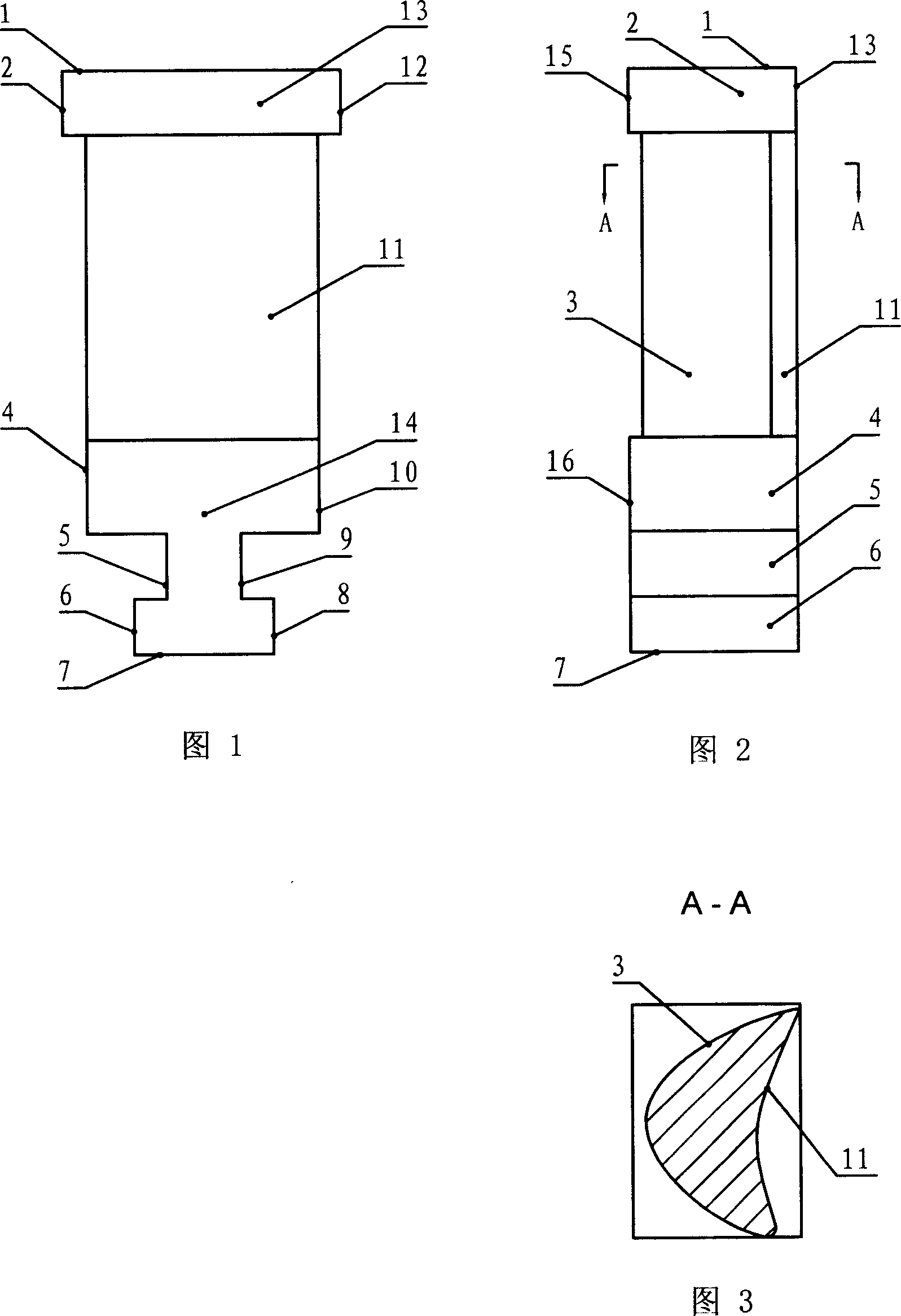
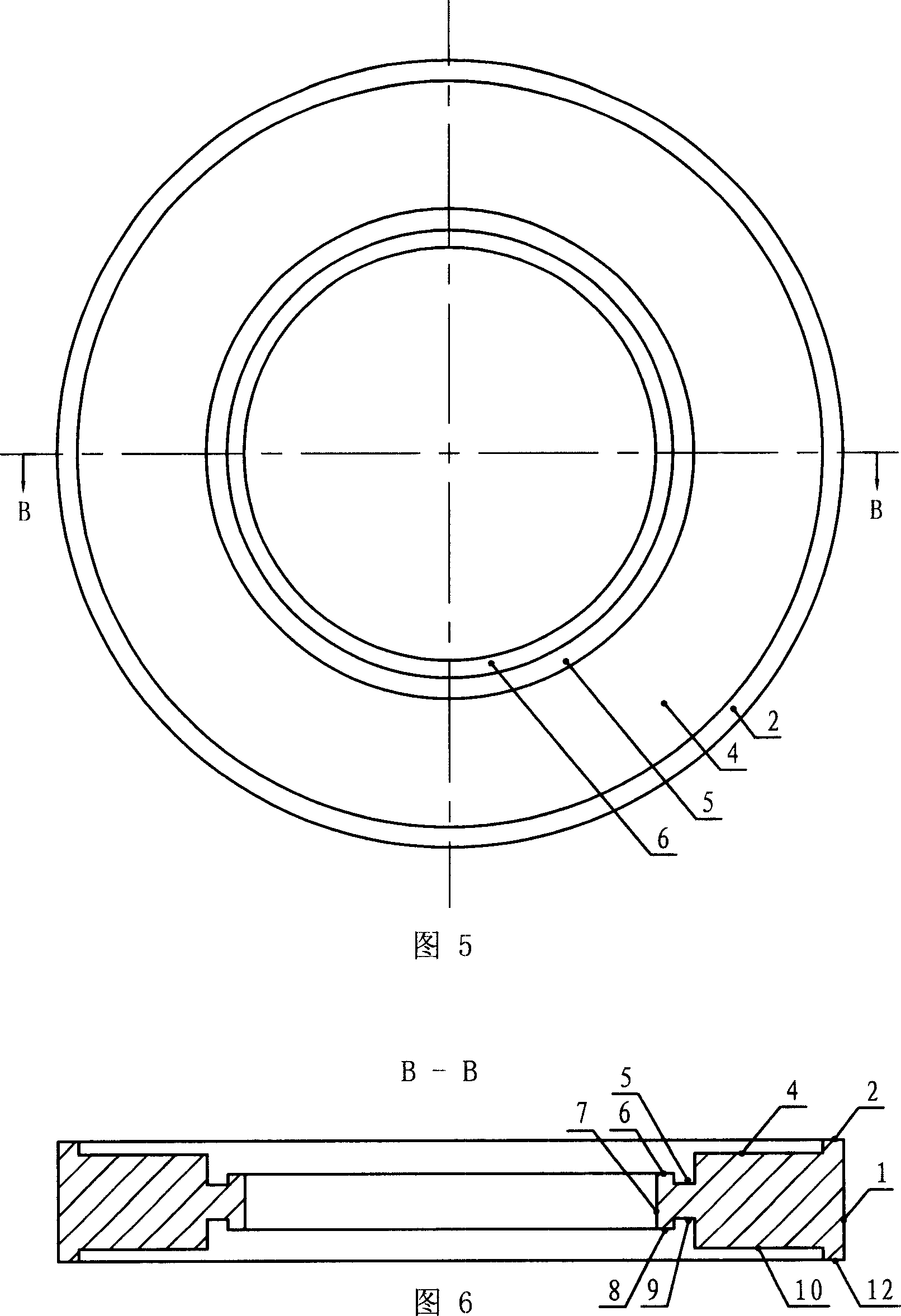
[0011] 1. Use a lathe to turn the ring-shaped blanks, and then turn each side of the blade-shaped workpiece on the two planes of the disk-shaped blanks to process the first and second planes of the blade-shaped workpiece. 2. The fourth plane 4, the first groove 5, the sixth plane 6, the seventh plane 7, the twelfth plane 12, the tenth plane 10, the second groove 9, and the eighth plane 8.
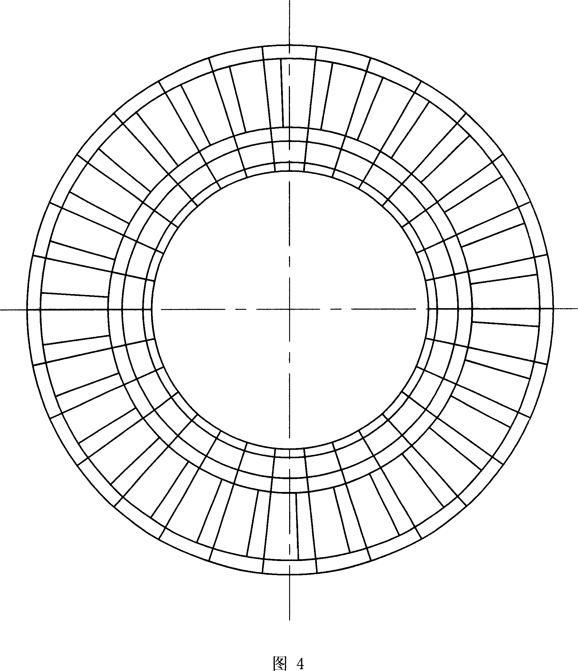
[0012] The ring-shaped blank in this step is made according to the shape of the ring formed after a number of blade-shaped workpieces are installed on the impeller. Figures 1 to 3 are schematic diagrams of the structure of the blade-shaped workpiece. When the impeller is filled with blade-shaped workpieces, the shape is as shown in Figure 4. The thirteenth plane 13 and the fourteenth plane 14 of a blade-shaped wor...

Example Embodiment

[0023] Embodiment 2: The difference between this embodiment and Embodiment 1 is that after step 3, step 4 is added, and step 4 is: polishing the milled inner arc surface 11 and outer arc surface 3.

Example Embodiment

[0024] Specific implementation manner 3: Refer to FIG. 11. The blade-shaped workpiece processing special tool of the present invention is composed of a base 20, a transmission shaft 22, a number of bearings 23, a shaft sleeve 24, a mounting plate 25 and a positioning pin 27. The base 20 is a fixed support of the special tool. The side surface 20-1 of the workpiece 20 is provided with a positioning hole 28, the positioning hole 28 can be clearance fit with the positioning pin 27, one end of the transmission shaft 22 is fixedly connected to the center position of the mounting plate 25, the plurality of bearings 23 Fixed between the transmission shaft 22 and the sleeve 24, the mounting plate 25 is a "convex" cross-section ring, and the convex part 25-1 in the middle of the mounting plate 25 can interact with the ring-shaped blank 30 to be processed. Clearance fit.

[0025] Before the wire cutting process, according to the number of blade-shaped workpieces that can be processed by the...


PUM


Abstract

The invention relates to a method for processing blade work piece, wherein it comprises 1, machining annular blank; 2, fixing the blank on special device, sing digit-control machine to process the semi product of single blade work piece; 3, milling inner and outer arc surfaces of semi product on milling machine. The inventive special device is formed by base, transmission axle, several bearings, axial sheath, and mounting disc and positioning pin; one end of transmission axle is connected to the center of mounting disc in cam ring; the protrusion part at the middle of mounting disc can match the blank. The invention has wide application.

Description

technical field [0001] The invention relates to a mechanical processing method and special tooling, in particular to a processing method and special tooling for blade-shaped workpieces of turbine machinery. Background technique [0002] Blade-shaped workpiece is one of the extremely important parts of turbine machinery, which is characterized by complex shape, high technical requirements and difficult processing. There are many types of blades, but all kinds of blades are composed of three parts: blade top, blade body (air passage part) and blade root (assembly part), and the blade body part includes an inner arc and an outer arc. The current processing method is to process a single rough blank one by one. Due to the complex shape of the blade-shaped workpiece, there are many surfaces to be processed, including multiple planes with the blade top and blade root, as well as the inner arc and outer arc of the blade body. The two arc surfaces of the arc need to be processed one...

Claims


Application Information

Patent Timeline
IPC IPC(8): B23H5/00B23H9/10B23Q3/00
Inventor 胡梁发
Owner 胡梁发
Why Eureka
Try Eureka