CO2 laser welding apparatus

A carbon dioxide and laser welding technology, applied in laser welding equipment, lasers, welding equipment, etc., can solve problems such as overheating of the weld, uneven weld, poor welding, etc., and achieve strong bonding and smooth welds.

Inactive Publication Date: 2007-05-16
HONG FU JIN PRECISION IND (SHENZHEN) CO LTD +1
View PDF0 Cites 4 Cited by
  • Summary
  • Abstract
  • Description
  • Claims
  • Application Information

AI Technical Summary

Problems solved by technology

[0005] In the above-mentioned condensation process, if the heat distribution is uneven and fast, it will cause local overheating at the weld seam, and eventually cause poor welding. The weld seam is not smooth from the outside, and the welding seam has insufficient bonding force

Method used


Image

  • CO2 laser welding apparatus
  • CO2 laser welding apparatus

Examples


Embodiment Construction

[0013] A carbon dioxide laser welding device will be described below with reference to figures.

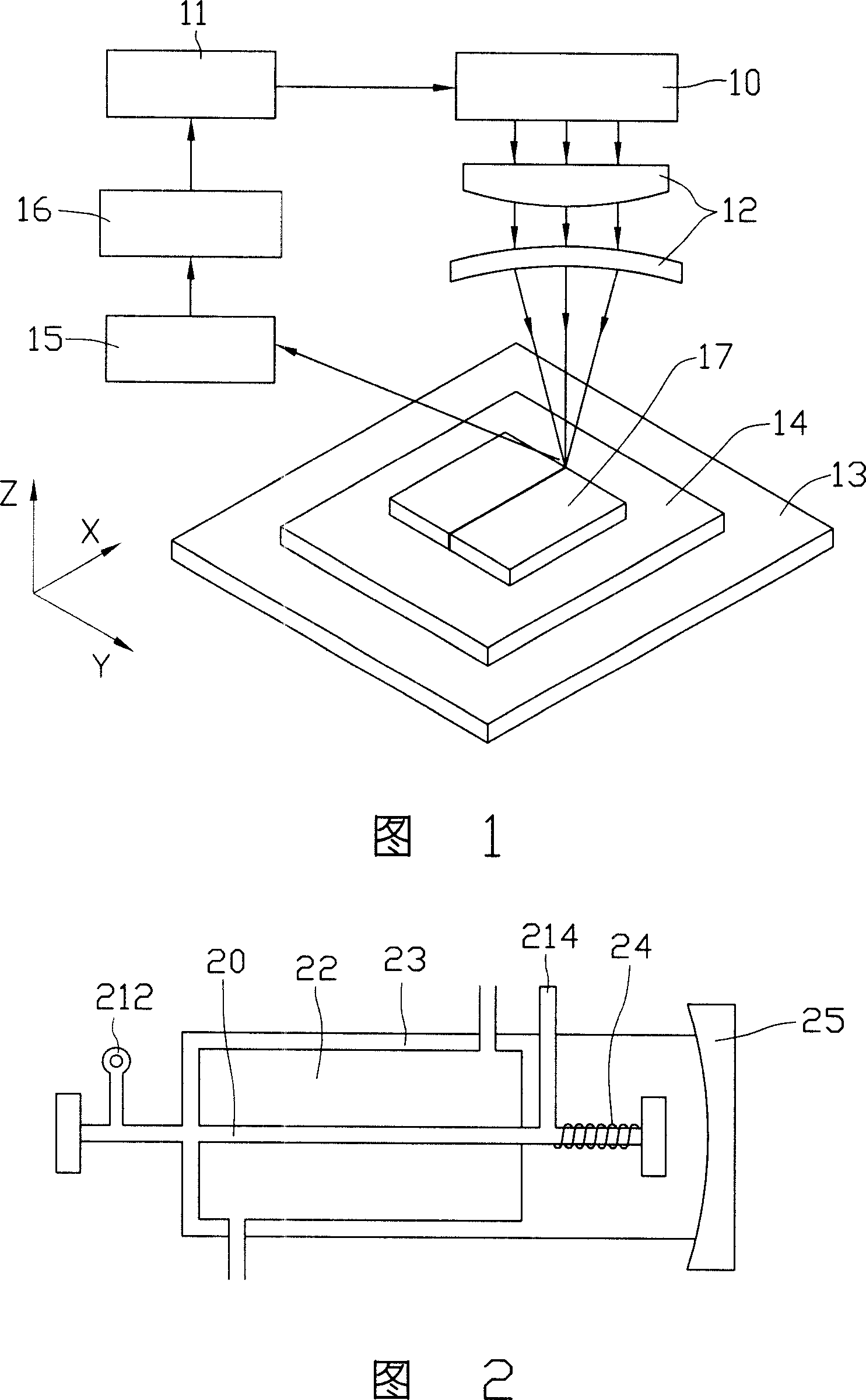
[0014] Please refer to FIG. 1 , the carbon dioxide laser welding device of the embodiment of the present invention includes a carbon dioxide laser 10 , a controller 11 , a lens system 12 and a stage 13 . Arrows in the figure indicate the direction of energy or signal transmission.

[0015] The carbon dioxide laser 10 is used to produce the high-energy laser beam needed for welding. Please refer to FIG. And the anode 214, the water cooling jacket 22 arranged on the surface of the discharge tube 20, and the gas storage sleeve 23 arranged outside the water cooling jacket 22. The discharge tube 20, the water cooling jacket 22 and the gas storage jacket 23 form a three-layer structure. The discharge tube 20 communicates with the gas storage sleeve 23 at one end close to the cathode 212 , and communicates with the gas storage sleeve 23 through the spiral air return pipe 24 at the othe...


PUM

PropertyMeasurementUnit
Pulse widthaaaaaaaaaa

Abstract

The invention relates to a carbon dioxide laser welding device, which comprises a carbon dioxide laser, a controller, a lens system, and a carrier, wherein said carbon dioxide laser can generate laser; the controller controls the laser; the lens system is used to focus the laser into the welding seam; the carrier has a cooler; when welding, the work piece is arranged on the cooler, then using the welding device to smoothen the welding seam, with strong combination.

Description

【Technical field】 [0001] The invention relates to a laser welding device, in particular to a carbon dioxide laser welding device. 【Background technique】 [0002] As a transparent material, glass is widely used in various computers and consumer electronics products, such as glass panels in various display screens. During the processing of glass, it is often encountered that two pieces of glass need to be welded together. [0003] Traditional welding methods include fusion welding, brazing, etc., fusion welding will have a more obvious weld seam, and brazing will introduce impurities. In the 1970s, laser welding began to be used, but it was mainly used for welding thin-walled materials. [0004] With the emergence of high-power carbon dioxide lasers, laser deep penetration welding can be applied in industry. When the laser is used for deep penetration welding, the high power density laser evaporates the material on the surface of the workpiece to form a small hole. The smal...

Claims


Application Information

Patent Timeline
IPC IPC(8): B23K26/20B23K26/04B23K26/42H01S3/10H01L35/16
CPCH01S3/041B23K26/0861B23K26/0648B23K26/423B23K26/032H01S3/2232B23K26/03B23K26/24B23K26/703
Inventor 陈杰良
Owner HONG FU JIN PRECISION IND (SHENZHEN) CO LTD
Why Eureka
Try Eureka