Dry method cement rotary kiln surface waste-heat utilization method and device
A technology of cement rotary kiln and dry process cement, which is applied in the steam generation method using heat carrier, cement production, rotary drum furnace, etc., to achieve good promotion value, convenient installation, and various functions.
- Summary
- Abstract
- Description
- Claims
- Application Information
AI Technical Summary
Problems solved by technology
Method used
Image

Examples
Embodiment 1
[0038] A method for utilizing waste heat on the surface of a dry-process cement rotary kiln, which is to install a plurality of heating devices on the outer surface of the cement rotary kiln, which have heating functions and produce medium and low pressure steam, so that the surface heat energy of the rotary kiln can be transferred through radiation and convection. The method is passed to the heat extraction device, the water or steam in it is heated, the steam generated from the heat extraction device is introduced into the steam turbine, and the generator is driven for waste heat power generation, or the steam is introduced into the steam engine as mechanical power or introduced into other places that need steam for waste heat use.
[0039] According to the structure of the cement rotary kiln, on the premise of not affecting the process and structure of the existing rotary kiln, the present invention adopts a cascade utilization method for the different surface temperatures o...
Embodiment 2
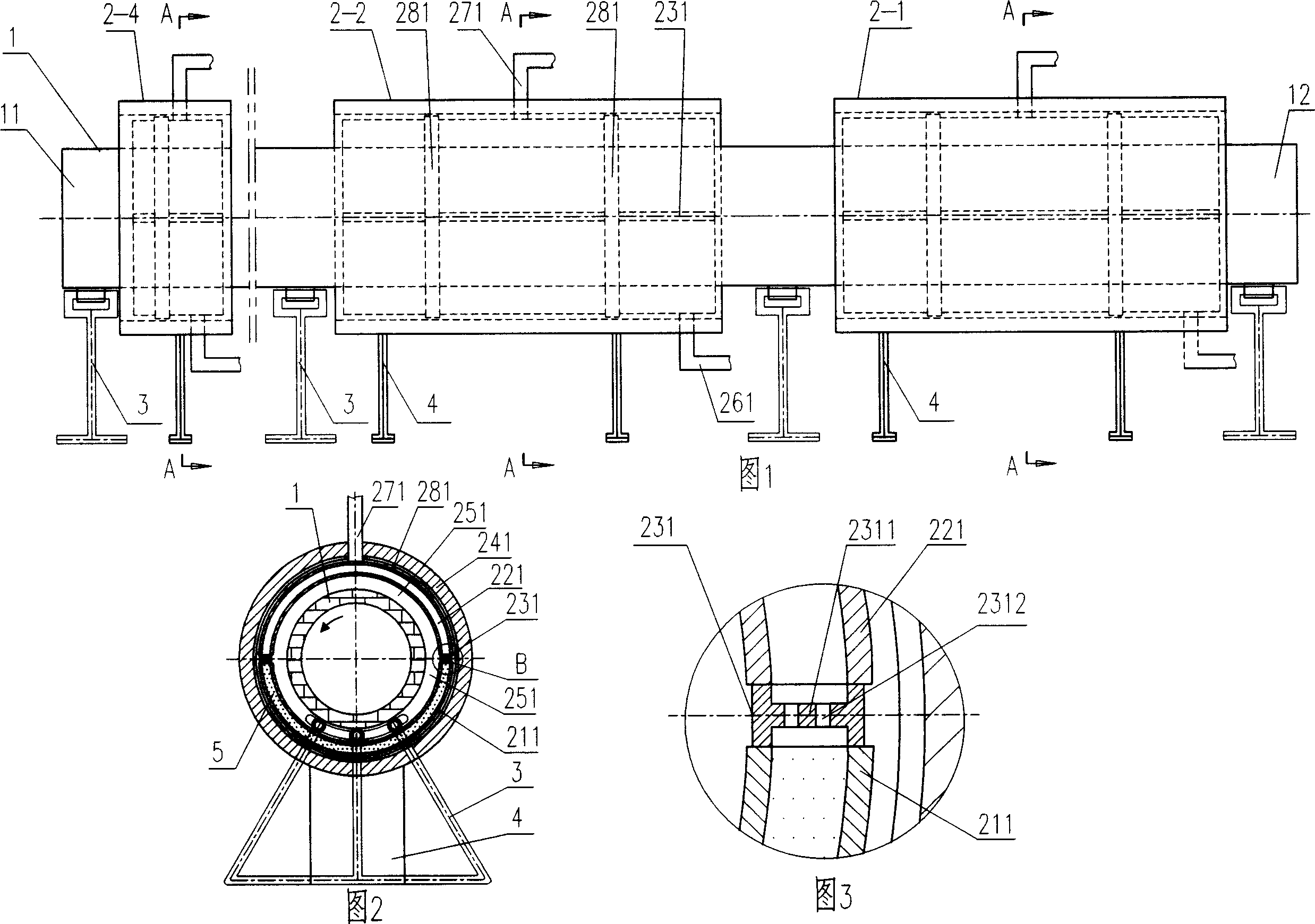
[0041] The method for utilizing surface waste heat of a dry-process cement rotary kiln is a device for utilizing surface waste heat of a dry-process cement rotary kiln in which an evaporator and a superheater are separated. As shown in Fig. 1 and Fig. 2, the device is composed of 4 heat-taking devices 2-1, 2-2, ..., 2-4, which are composed of a sealed hollow shell that surrounds the outer surface of the rotary kiln and functions as an evaporator and a superheater. There is a small gap 251 between the sealed hollow shell and the rotary kiln shell, and the superheater and evaporator of each heat-taking device are respectively composed of the upper half of the sealed hollow shell that acts as a superheater and the sealed hollow shell that acts as an evaporator. The lower part of the hollow shell is composed of (see Figure 1 and Figure 2). There is a water inlet pipe or an air inlet pipe 261 at the lower part of the evaporator 211, and an air outlet pipe 271 at the upper part of th...
Embodiment 3
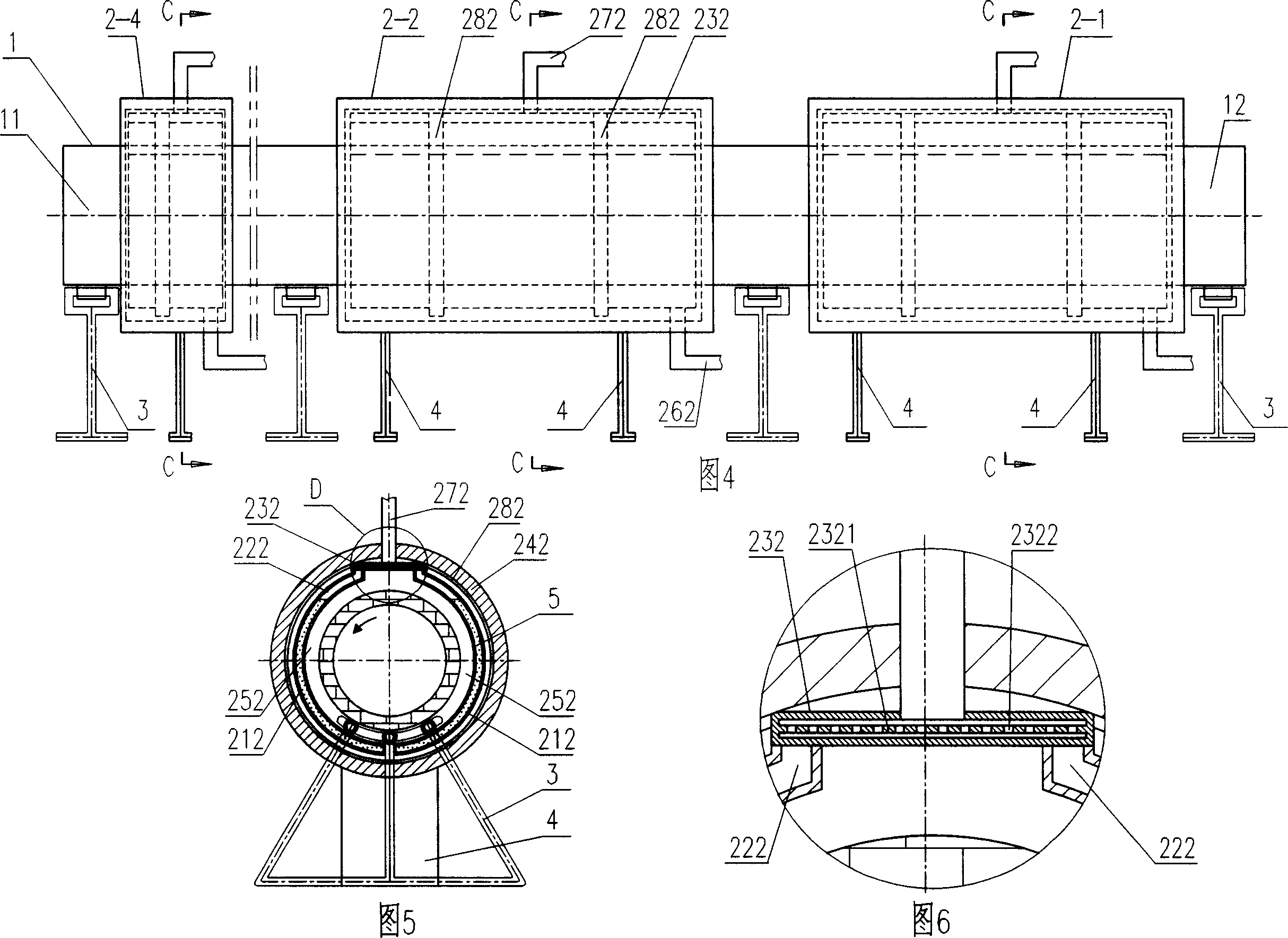
[0043]Another device for utilizing the surface waste heat of the dry-process cement rotary kiln adopted in the method for utilizing the surface waste heat of the dry-process cement rotary kiln. As shown in Figures 4 to 6, the device is composed of four heat-taking devices 2-1, 2-2, ..., 2-4, which are composed of a sealed hollow shell that surrounds the outer surface of the rotary kiln and acts as an evaporator and a superheater. Each of the heat-taking devices is composed of sealed hollow shells that surround the front and rear sides of the rotary kiln, the bottom of each sealed hollow shell is sealed, and the upper half of the front and rear parts The 1 / 4~2 / 4 part of the upper part is the superheater 222 which acts as a superheater, the lower 2 / 4~3 / 4 part is the evaporator 212 which acts as an evaporator (see Figure 4), each sealed hollow shell The body is filled with water, and the height of the water is 2 / 4 to 3 / 4 of the height of the sealed hollow shell. The upper part of...
PUM
 Abstract
Description
Claims
Application Information
 - R&D
- Intellectual Property
- Life Sciences
- Materials
- Tech Scout
- Unparalleled Data Quality
- Higher Quality Content
- 60% Fewer Hallucinations
Browse by: Latest US Patents, China's latest patents, Technical Efficacy Thesaurus, Application Domain, Technology Topic, Popular Technical Reports.
© 2025 PatSnap. All rights reserved.Legal|Privacy policy|Modern Slavery Act Transparency Statement|Sitemap|About US| Contact US: help@patsnap.com