Photonic crystal waveguides and medical treatment systems containing the same

A photonic crystal fiber, gas technology, applied in the direction of bundle optical fiber, can solve the problem of incompatibility, and achieve the effect of low loss

Inactive Publication Date: 2007-06-06
全波导公司
View PDF13 Cites 20 Cited by
  • Summary
  • Abstract
  • Description
  • Claims
  • Application Information

AI Technical Summary

Problems solved by technology

However, conventional optical fibers are generally unsuitable for applicat

Method used


Image

  • Photonic crystal waveguides and medical treatment systems containing the same
  • Photonic crystal waveguides and medical treatment systems containing the same
  • Photonic crystal waveguides and medical treatment systems containing the same

Examples


Embodiment

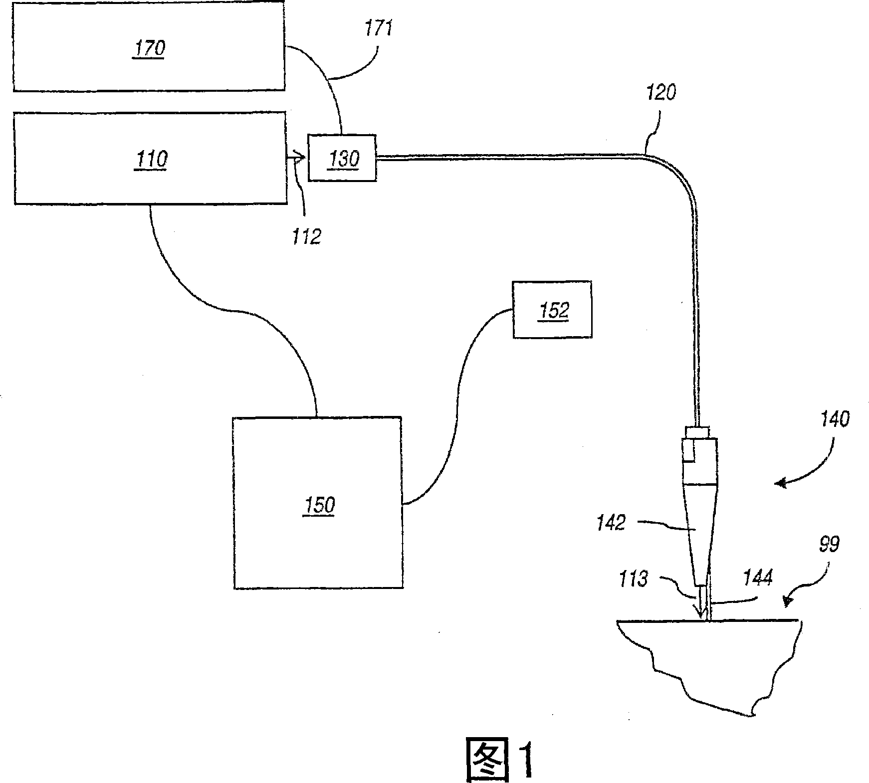
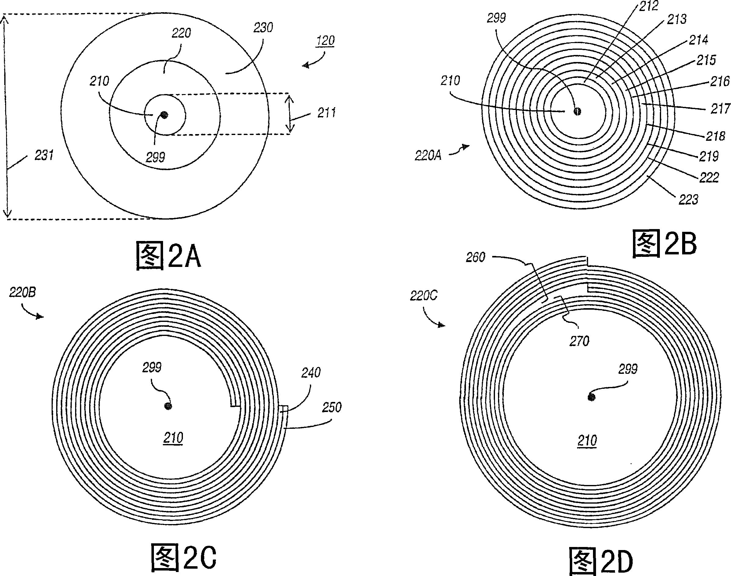
[0251] Utilizes CO operating at 10.6 microns 2 A laser system performs the surgical removal of multiple parts of the larynx from the dog. The photonic crystal fiber used in this process has a hollow core with a diameter of approximately 550 microns. The fiber has a helical confinement region comprising approximately 20 PES / As 2 Se 3 Radial section of a double layer. The thickness of the double layer is approximately 3 microns, and the thickness ratio is approximately 2 to 1 (PES to As 2 Se 3 ). The cladding of the fiber is formed of PES, and the OD of the fiber is approximately 1500 microns. The optical fiber is 1.5 meters long.

[0252] A complete en bloc glottic laryngectomy, which includes a cordectomy, is performed. Laser radiation is delivered using a photonic crystal fiber with a semi-rigid handpiece. Insert the handpiece and pass it through the rigid laryngoscope. The power input into the fiber is approximately 20 watts. The radiant power output from the fibe...


PUM


Abstract

In general, in one aspect, the invention features systems, including a photonic crystal fiber including a core extending along a waveguide axis and a dielectric confinement region surrounding the core, the dielectric confinement region being configured to guide radiation along the waveguide axis from an input end to an output end of the photonic crystal fiber. The systems also includes a handpiece attached to the photonic crystal fiber, wherein the handpiece allows an operator to control the orientation of the output end to direct the radiation to a target location of a patient.

Description

[0001] Cross-references to related applications [0002] This application claims Provisional Patent Application No. 60 / 560458, filed April 8, 2004, entitled "PHOTONIC CRYSTAL FIBER APPLICATIONS," under 35 USC § 119(e)(l); 2004 The provisional patent application No. 60 / 561020 filed on April 9, 2004, entitled "PHOTONIC CRYSTAL FIBER APPLICATIONS"; the provisional patent application No. 60 / 584098 filed on June 30, 2004, Patent application entitled "PHOTONIC CRYSTAL FIBER APPLICATIONS"; Provisional Patent Application No. 60 / 628462, filed November 16, 2004, entitled "PHOTONIC CRYSTAL FIBER APPLICATIONS" Application; Provisional Patent Application No. 60 / 640536, filed December 30, 2004, entitled "CO 2 OMNIGUIDE PHOTONIC BANDGAP FIBERS FOR FLEXIBLEDELIVERY OF CO 2 LASERS IN LARYNGOLOGY), and Provisional Patent Application No. 60 / 658,531, filed March 4, 2005, entitled "PHOTONIC CRYSTAL FIBER." All provisional patent applications listed above The contents of are hereby incorporated by...

Claims


Application Information

Patent Timeline
IPC IPC(8): G02B6/06
Inventor 布拉克·泰梅尔库兰哈拉兰博斯·阿纳斯塔索戴维·托里斯吉尔·沙皮拉马克斯·舒尔加林格雷戈尔·德莱曼奥里·韦斯伯格史蒂文·A·雅各布斯王泰然尤里·科洛德内杰西·腊斯科罗伯特·佩恩约尔·芬克格克汗·乌卢
Owner 全波导公司
Why Eureka
Try Eureka